The schematic you're talking about is this one? http://www.raylectronics.nl/pdfs/CD_outputstage_PCB.pdf
Well its losing as far as I can see pretty much all of the advantage of using JFETs because its input impedance is still very low (single digit kohms).
It's very similar to that schematic. Same author.
Found during a google search on "discrete output".
I'll send a message with it linked.
Got some work done on the "Abraxalito buffer-filter-buffer" board today.
The Pavouk.org filter/buffer is done.
Two of the shunt regs are done.
Started on:
Abraxalito buffer-filter-buffer board
WM8740 board, about 75% done
Two versions of DIR9001 board
Power supply/capacitor bank board, about 80% done
Not yet started:
Jfet balanced to SE buffer followed by a discrete filter/buffer - Thanks mr. Abraxalito, you are a great source of help and inspiration.
Two more low current shunt regs to start on and a dual rail +/-12Vdc shunt reg that I have yet to get the simulations right for.
Finished the "Abraxalito", well apart from final mounting and wiring.
The buffer-filter-buffer for the WM8740 in other words, thanks man it's hugely appreciated!
One board(4x6cm) per channel for the pre-filter buffer, Rpos, Rneg on one board etc

Filter, post-filter-buffer and capacitor board (two caps are on the bottom of the PCB)

not pretty, but no shorts and connection where there should be(leftover solder is from removing SMD's)

Mock-up to check wire lengths etc


So the project is far from dead 🙂
The Pavouk.org original filter/buffer is built as well.
Love those stacked 4*6's 😀 I've been populating some 5*7's and imagining them stacked....
Thanks mate!
Love the dual side plated through perf boards.
They make layout etc much more easy, I can "tac" parts on the topside to keep them in place while doing wiring on the bottom side.
I've got more 4*6 and 5*7 on the way.
Figured I have more space upwards than sideways so to speak.
Plus the whole point of this project is for it to be as modular as possible.
Its amazing how many transistors'll fit on one of these - here's my latest 7*5 under construction. At present it has a stereo pair of 6th order filters (Cs and Rs yet to be fitted) - 42 transistors, using the 'discrete' darlingtons. To be added are a stereo I/V and then if there's still space, the DAC chip and power supply.
Attachments
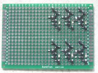
Its amazing how many transistors'll fit on one of these - here's my latest 7*5 under construction. At present it has a stereo pair of 6th order filters (Cs and Rs yet to be fitted) - 42 transistors, using the 'discrete' darlingtons. To be added are a stereo I/V and then if there's still space, the DAC chip and power supply.
I couldn't keep track of what goes where when trying to do the buffer with smd's, that was my problem...not soldering small parts.
Conclusion: my head gave in before my hands lol
Started over on the WM8740 board, the perf board I was using was useless. Very hard to get good solder joints on.
Decided to go with smd's and do the WM8740 on a 4*6cm double sided perf board.
Should hopefully have the parts needed to finish the smd DIR9001 board and the different discrete options for output.
Also still have to do a few more shunt reg boards.
I was thinking atleast two of each (3.3Vdc and 5Vdc), one for digital supply and one for analog supply.
Attachments
Time to post some progress 🙂
DIR9001 mkI board is done


DIR9001 mkII is getting there 🙂
The SN75176BP is under the TSSOP28 - DIP28 adapter.

The board needs a good cleaning when done..no clean solder and flux...hmm 😉

WM8740 mkII (since I started over on a different board, and swapped some components)
Connectors are on their spots, just to keep track of them. I'll solder wire to them later


The "original" (in quation as the original BOM is with SMD's) Filter/buffer


I've got two of the Vregs done, but not yet tested

Then of course there's the Abraxalito buffer-filter-buffer 🙂
All that is left to do here is the wiring, test it and pop in an OPA2134

Old-ish picture where the mounting is just a mock-up to see if my idea worked.

This, some work on the rectifying-cap-bank-board, xformers mounted in chasssis and parts for yet another filter/buffer solution sorted and put in a zip-lock bag is as far as I've gotten.
Waiting for parts to arrive is what is keeping the pace reasonable, thank god.
I also have an AD1896A that I've soldered to an adapter, so I'll include the option to have ASRC in the modular dac.
On it's way is a WM8805 IC and alot of the double sided perf boards, that are great btw, an 12Mhz crystal for WM8805 and a 24.576Mhz crystal for the AD1896A.
I have a few TDA1541A at home, so I might build a module for one of those along with a module for I/V.
That's it for now 🙂
Hopefully there will be more parts in the mail tomorrow.
A special thank you goes out to Abraxalito, you are truly a great help and very kind to share your knowledge!
Some work done today, not much though as I wait for parts to get here.
Wiring between Vregs and WM8740, DIR9001 etc

Mock-up of DIR9001 and WM8740 boards stacked


Two of the shunt regs stacked, also just a mock-up


DIR9001 board with the SN75175BP in place, taken with my phone.

Hopefully more parts will arrive this week.
Wiring between Vregs and WM8740, DIR9001 etc

Mock-up of DIR9001 and WM8740 boards stacked


Two of the shunt regs stacked, also just a mock-up


DIR9001 board with the SN75175BP in place, taken with my phone.

Hopefully more parts will arrive this week.
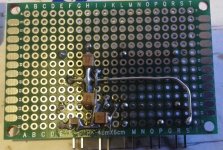
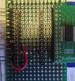
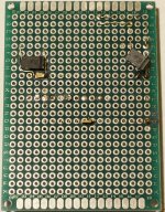
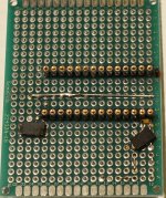
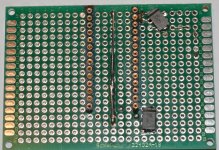
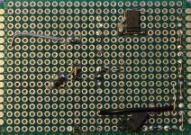
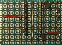
Got the second DIR9001 board done today, except for extensive fault finding/testing...but I save that for when I'm less tired.
Bottomside

Topside

DIR9001 on adapter-board, Voltage supervisor soldered directly to adapter-board. These boards where apparently specificly made for DIR9001, I did however solder them myself using an iron.

Bottomside of adapter-board, the signs of things soldered in the wrong place still there lol

This makes two done DIR9001 boards, apart from one more look/measuring so everything is OK.
The WM8740 board is done as well apart from the same as above.
Two different solutions for Filter/Buffer are done, apart from some wiring etc.
Still to do:
OPA2111KP Balanced to SE + discrete filter/buffer board
WM8805 reciever board (to compare to the DIR9001's)
PCM1794 D/A board (to compare to WM8740)
I/V for the above D/A IC.
AD1896 board to compare with/without ASRC(thought I'd try up/down-sampling all material to 96Khz).
More work on the power supplies: More reg boards etc.
Refine layout in the enclosure and drill out more holes.
Might do:
TDA1541A board.
Once again a shoutout to Abraxalito without his help I would never have gotten this far...atleast not any time soon. Thanks man, I really appreciate it 🙂
Since I've added the WM8805 to the list of swappable modules for this dac, I have a question.
I've read that some use a pulse transformer followed by a 74HC04 for the spdif input, how would that schematic look?
For the DIR9001 boards, I use 75R across input followed by a PE-65612 followed by a SN75176BP.
This is not optimal for the WM8805?
Also, per abraxalito's advice, I've added the TDA1387 to the list of D/A IC's to swap between. Ordered 5pcs, so balanced + parallel comes to mind...
Got started on the AD1896A board today.
So far only the 3.3Vdc LDO for the 24.576Mhz crystal oscillator has been populated:
Did some more work on the OPA2111KP balanced to SE + discrete filter board:
(The long black GND connector wire will be replaced as it is simply too ugly as is)
In my opinion 0805 or 0603 are the perfect size SMD's for these double sided perf boards. 1206 are a bit big, 0603 almost to small.
So far only the 3.3Vdc LDO for the 24.576Mhz crystal oscillator has been populated:
An externally hosted image should be here but it was not working when we last tested it.
An externally hosted image should be here but it was not working when we last tested it.
Did some more work on the OPA2111KP balanced to SE + discrete filter board:
(The long black GND connector wire will be replaced as it is simply too ugly as is)
An externally hosted image should be here but it was not working when we last tested it.
An externally hosted image should be here but it was not working when we last tested it.
An externally hosted image should be here but it was not working when we last tested it.
An externally hosted image should be here but it was not working when we last tested it.
An externally hosted image should be here but it was not working when we last tested it.
In my opinion 0805 or 0603 are the perfect size SMD's for these double sided perf boards. 1206 are a bit big, 0603 almost to small.
About the AD1896A board:
Since I already have the 2pin 24.5760Mhz HC-49S crystal oscillator (2pcs),
and I'll put the one I use in a socket(they do age)...I was wondering if I could use that crystal to MCLK_I.
Audio Design Guide
Either as shown in the schematic in the link above or between MCLK_I and MCLK_O with one 12pF capacitor to GND on each side.
The AD1896A board will be set as ASRC to up-/down-sample all source material to 24bit 96Khz. 90% of the time I listen to 44.1Khz material anyway.
So, I want:
I2S
24Bit
256fs (gives 96Khz with 24.5760Mhz)
The AD1896A board will be between the reciever board(DIR9001 or WM8805) and the D/A board (WM8740 or PCM1794)
In the case with the WM8805, it has it's own 12Mhz crystal oscillator. Should that be omitted when using ASRC?
I guess I should set the AD1896A board like this?
SMODE_I
2: L
1: L
0: H
I2S
SMODE_O
1: L
0: H
I2S
WLENGHT_O
1: L
0: L
24bit
MMODE_O
2: L
1: H
0: H
256fs Output serial port is Master
Or am I misunderstanding something, missing something?
0603 resistors nowadays are almost unimaginably cheap - a reel of 5000 pieces is under $2 and a book of 8500 of various values is just about $10 - https://detail.tmall.com/item.htm?spm=a230r.1.14.9.8VfNix&id=25180164441&cm_id=140105335569ed55e27b&abbucket=1
0603 resistors nowadays are almost unimaginably cheap - a reel of 5000 pieces is under $2 and a book of 8500 of various values is just about $10 - https://detail.tmall.com/item.htm?spm=a230r.1.14.9.8VfNix&id=25180164441&cm_id=140105335569ed55e27b&abbucket=1
That sample book looks very interesting!
Do they accept paypal at taobao?
Having some real trouble with the non-translated pop-up windows lol
No, they only accept AliPay, their own form of PayPal (with lower fees). I wonder if Aliexpress has any similar offers......
Yes but the 'free shipping' must be rolled into the price as its $30 : http://www.aliexpress.com/item/Free-shipping-0603-SMD-Resistor-Sample-Book-1-Tolerance-170valuesx50pcs-8500pcs-Resistor-Kit-0R-10M/32253986320.html?spm=2114.01020208.3.11.hWDgZX&ws_ab_test=searchweb201556_2_91_71_72_73_74_75,searchweb201644_5,searchweb201560_9
Yes but the 'free shipping' must be rolled into the price as its $30 : http://www.aliexpress.com/item/Free-shipping-0603-SMD-Resistor-Sample-Book-1-Tolerance-170valuesx50pcs-8500pcs-Resistor-Kit-0R-10M/32253986320.html?spm=2114.01020208.3.11.hWDgZX&ws_ab_test=searchweb201556_2_91_71_72_73_74_75,searchweb201644_5,searchweb201560_9
No, they only accept AliPay, their own form of PayPal (with lower fees). I wonder if Aliexpress has any similar offers......
Yes but the 'free shipping' must be rolled into the price as its $30 : Free shipping 0603 SMD YAGEO Resistor Sample Book 1% Tolerance 170valuesx50pcs=8500pcs Resistor Kit 0R~10M-in Resistors from Electronic Components & Supplies on Aliexpress.com | Alibaba Group
Any way of simply paying with credit card as I've done on aliexpress when ordering water cooling parts for the PC.
Having trouble registering as I get an error message after dragging the slider to the right.
Small update.
I've started building the PCM1794 board.
I've ordered the few parts I didn't have for building some Jung/Didden super regulators. Not sure where they'd be best implemented (don't want to use more than two in this project to begin with).
Also got started on the AD1896A board and the WM8805 board.
Still need to figure out if the WM8805 should have it's oscillator connected when using the ASRC, what settings to use to up-/downsample all source material to 24bit 96Khz (using 24.576Mhz oscillator).
Edit: the wire used as sowing thread is 0.3(or 0.4, don't remember) 99.99% silver wire.
Attachments
Last edited:
- Status
- Not open for further replies.
- Home
- Source & Line
- Digital Line Level
- Wm8740, possible discrete filter/buffer?