I got a few parts today, I'm almost set to build the dir9001 board and the pavouk version filter/buffer. IIRC, I only need a few capacitors and one or two value resistors.
I'll build both Abraxalito buffer-filter-buffer and the original schematic one.
With the wm8740 on it's own board and filter/buffer on it's own board(s) I'm free to swap between the filter/buffer boards.
I might even be able to swap DAC IC with the dir9001 having it's own board etc.
Waiting for the Bc817-40, sot23-3 adapter boards and a few other small parts before I can build the abraxalito board.
Also still waiting for the wm8740 IC itself.
In the meantime I'm trying to figure out voltage regulators, if I should build the AD1896A board and if so how to configure it.
It's a educational and fun project 🙂
Hi 🙂
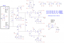
One solution for the 0 DC buffer at output of the Votage dacs WM8740/1
I used this type of DAC buffer-filter-driver interstage.
The simple circut adjustable is for making 0 DC at output.
Very soft filter Philips style is aplied.
I am using only positive branch with transformer output.
Also, some buffer is very welcome after the trafo, which I did not put yet...🙂
but is working well, and easy to set. L are from ferrite beads.
Only You have to check and adjust Io to the JFETS, because it is differs from simulations and spice models in real world. But it is 10min job.
Cheers
Attachments
How do you get 1.1mH out of ferrite beads? I'm very curious to learn as the beads I've measured have all been around 1uH.
Hi 🙂
One solution for the 0 DC buffer at output of the Votage dacs WM8740/1
I used this type of DAC buffer-filter-driver interstage.
The simple circut adjustable is for making 0 DC at output.
Very soft filter Philips style is aplied.
I am using only positive branch with transformer output.
Also, some buffer is very welcome after the trafo, which I did not put yet...🙂
but is working well, and easy to set. L are from ferrite beads.
Only You have to check and adjust Io to the JFETS, because it is differs from simulations and spice models in real world. But it is 10min job.
Cheers
Thanks for the suggestions 🙂
I'll stick with the Pavouk.org filter/buffer and Abraxalito buffer/filter/buffer for now.
Abraxalito:
About the buffer output caps...
What value (Min) can I use if using filmcaps?
So that I don't create a filter for the audio signal, cutting the low end.
About the buffer output caps...
What value (Min) can I use if using filmcaps?
So that I don't create a filter for the audio signal, cutting the low end.
1.1mH is 2 x 2.2mH in Parallel acc.
Each FB or litle choke of 2.2mH that I pick up in local store (like resistor packages...)
have acc of 12ohm dc res.
.
Or You can mount own better L with lower DC res and better Q, that is just for the try.
Latter L can be replaced...
.
http://www.google.com/search?q=2.2m....1.1.0....0...1ac.1.34.img..2.0.0.-rFJS0dk81o
.
http://www.google.com/search?q=2.2m...j1.1.0....0...1ac.1.34.img..5.0.0.lviLkpCHU-4
.
Last edited:
I post it like example of buffer for DACs have DC offset (Vmid) of 1/2 Vanalog at the output... That is the main point. To acheive 0V offset without C coupling like in Your example. I build it and it is working.
.
This is the most simple circuit. I use simple TL431 to get reference for 2.5V,
same as Vmid pin for WM dacs...
.
This is the most simple circuit. I use simple TL431 to get reference for 2.5V,
same as Vmid pin for WM dacs...
What value (Min) can I use if using filmcaps?
So that I don't create a filter for the audio signal, cutting the low end.
It depends what the load impedance is of your pre/amp. The capacitor forms a high-pass filter with the input resistance of the downstream component. If its 100k you could get away with as low as 220nF. If 10k then 2.2uF I'd suggest.
It depends what the load impedance is of your pre/amp. The capacitor forms a high-pass filter with the input resistance of the downstream component. If its 100k you could get away with as low as 220nF. If 10k then 2.2uF I'd suggest.
Will run my BCL clone headamp and maybe the "JHL" class A headamp I'm waiting for of the DAC.
BCL - inputs goes straight to vol.pot which is 50K.
JHL - I think is the same but 10K
I've got some 6.8uF MKP x-over caps that could be used then.
To bad I sold my leftover PIO caps, I really like the old russian military NOS PIO's.
Hi Zoran,
I'm curious how this active output circuit performs compare to the fully passive 1:1 transformer balanced output.
I'm curious how this active output circuit performs compare to the fully passive 1:1 transformer balanced output.
That is an interesting question.
And can you swap loads with the xformer output?
My edcor's in my CS4398 dac are "configured" for a 50K load.
And can you swap loads with the xformer output?
My edcor's in my CS4398 dac are "configured" for a 50K load.
I think(may be wrong) that I'm making progress on the CS-Vreg design for the low current loads.
This is very much thanks to members on this forum helping me. Thanks guys 🙂
This is very much thanks to members on this forum helping me. Thanks guys 🙂
The project is not dead 🙂
Assuming that this project is still not dead I'm pleased to report I tried out applying some of my suggested mods to a WM8740 DAC I just acquired. Stock it had the 2k4 and 150R resistor circuit, along with 3n3 and 680pF capacitors. SQ was nothing special at all.
I increased the impedance of all the components around the off-chip opamp (which was originally an LM4562, I swapped this to an ISL28210 low current noise JFET) by a factor of 100. So 2k4 became 240k, 3n3 became 33pF and 680pF became 6.8pF, 150R became 15k.
The result was a fairly massive improvement in LF dynamics. I put this down to the PSRR of the 8740's internal opamps (CMOS type) being improved when driving high impedance loads. The HF quality of S-D converters that I avoid was still present on complex music (orchestral strings, massed choirs). I'm looking into ways of ameliorating the ragged HF but the LF improvement was just short of staggering 😀
Not dead at all 🙂
I'm waiting for parts, but have started on some of the boards.
I've started one Pavouk.org board(filter-buffer), one Abraxalito board (buffer-filter-buffer), two DIR9001 boards (one with filmcaps, one with SMD), I've started on the PS boards etc.
The OPA2134 part of the Abraxalito filter-buffer-filter was built using 100K and 6K2 resistors as suggested earlier, 82pf and 15pf X7R smd caps.
I'm waiting for a few more SOT23-3 adapters and a few resistors before I can build the BC817-40 pre and post 2134 buffers.
I was going to ask you: Out from the WM8740 there are 2K4 resistors(4pcs) and in to the pre buffer(after the ferrite beads) there are 4R7 resistors, this is ok?
The DIR9001 board that'll get SMD caps
It's been a while since I soldered TSOP28, but I think it went OK.

Pavouk.org filter board(Huge Riken resistors on outputs)

Last edited:
I have a question,
Would it matter for SQ if I build the buffers with BC548/BC547 instead of the BC817-40's?
It just looks horrible when doing smd on perf board.
I have over 60pcs of each and about 30pcs of the 817's.
I have the option of using 220uF Muse, 4.7uF Aerovox(x2/channel) or 6.8uF audiophilier (something like that, got them long ago of ebay) as output caps on the post-2134 buffer.
What would be the best choise?
I can't think of any reason at all that leaded transistors wouldn't sound as good as SMT ones. On caps, I'm a heretic and don't use any kind of fancy brand so I'm not really qualified to comment. I'd use the smallest...
I think I'll go with the 2x 4.7uF caps/channel.
They are ok and smaller than the mkp's I have.
I'll build with bc547's then.
Thanks
They are ok and smaller than the mkp's I have.
I'll build with bc547's then.
Thanks
I almost forgot, I found another schematic for a discrete output buffer.
I'll probably build both and compare as they are a bit different.
I'll link the site when I get home, interested in your thoughts on it.
I'll probably build both and compare as they are a bit different.
I'll link the site when I get home, interested in your thoughts on it.
Forgot to link the page yesterday.
Looking at both the BJT output and the J-fet output
Ray's Audio Page
I found the schematic through a google image search.
It's not identical to the ones in PDF on the site linked above.
I don't know if it's OK for me to post my Spice schematic with .op here?
If not, I can PM you the schematic I did the sim with.
Since it is a discrete CD-player output, could I hook it up right to the 2K4 resistors on the outputs of the WM8740? The discrete circuit has two inputs and one output.
However, since all those CD-players have TDA1541's, I'm concerned about possible I/V in the schematic and what impact that would have since WM8740 is a Vout DAC.
The schematic you're talking about is this one? http://www.raylectronics.nl/pdfs/CD_outputstage_PCB.pdf
Well its losing as far as I can see pretty much all of the advantage of using JFETs because its input impedance is still very low (single digit kohms).
Well its losing as far as I can see pretty much all of the advantage of using JFETs because its input impedance is still very low (single digit kohms).
- Status
- Not open for further replies.
- Home
- Source & Line
- Digital Line Level
- Wm8740, possible discrete filter/buffer?