Just got my measurement preamp kit from highefficiencyloudspeakers.com.
The wm-61a pana. mic capsule seems to be very peaky from 10khz and up, is it due to my poor soldering skills? bad capsule? or is it a normal thing and I can calibrate it??
I'm still trying to figure out speakerworkshop to do simple FR for now. So far, I consistently get measurements with peaks above 10khz.
Help!!!!
This is the response of my WM61a mic capsule...although it's about a 5 year old model. I also have a second one, which is the same shape but about 1 dB lower at the peak.
An externally hosted image should be here but it was not working when we last tested it.
jbateman said:This is the response of my WM61a mic capsule...although it's about a 5 year old model. I also have a second one, which is the same shape but about 1 dB lower at the peak.
An externally hosted image should be here but it was not working when we last tested it.
Hi jbateman,
Can you please tell me where can I find the generic calibration files of the WM-61A?
I'm a bit confused, the plot you posted, is the actually frequency response of the capsule or the calibration files for correction?
If these are the calibration files then the capsule should starting to roll off at about 5KHz, right?
Padel
Hi sqlkev,
I've been having problems with peaky response too (wm60YA mic capsule). I have got some good results, but I haven't been able to get them consitently. Soldering could be an issue, I got good results after resoldering the capsule, but then it went bad again.... I think I was so worried about overheating the capsule that I didn't solder it properly...
I'm still trying to track down the problem.... I'm going to build a new preamp on one of Vikash's boards, I have the same preamp I made on an ic experimenter board, and want to make sure the problem isn't with my preamp.
Are you doing gated measurements in SW? and if so, are you setting the gate interval properly? If you don't correctly set the gate interval, then you will get very nasty freq response curves due to reflections....
here ---> http://www.akustyk.com/pomiary/hardware/Eric Wallin's Internet Homepage - preamp2.htmis what Eric Wallin measured on a number of WM61A's scroll down till you get to the f/r graph.
You could try downloading a generic WM61A callibration file.... I think that since the mics are good up to 5K you can confidently use it for crossover design provided you aren't crossing higher than 5K
Tony.
Padel said:
Hi jbateman,
Can you please tell me where can I find the generic calibration files of the WM-61A?
I'm a bit confused, the plot you posted, is the actually frequency response of the capsule or the calibration files for correction?
If these are the calibration files then the capsule should starting to roll off at about 5KHz, right?
Padel
I had my mic calibrated many years ago by Kim Girardin of Liberty Instruments. The picture is the actual frequency response of the mic.
When the mic is calibrated, you receive an FRD file, which you import into your SpeakerWorkshop project directory. Then when you open the OPTIONS/CALIBRATE tab, there is a box to browse to the mic cal file. SW then use this data to apply a correction to any acoustic measurements you make.
If you want to try my cal file, I will try to attach it as a TXT file (bateman.txt). You will have to rename it to an FRD file (anything.frd) in order to use it, though.
Attachments
Hi jbateman,
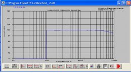
Thank you very much for .frd files, unfortunately they are not compatible with the ETF 5.0 measuring software that I'm using right now. ETF accepts .cal files and I tried to rename as such with no luck.
Anyway, here is a response graph of a generic WM61A .cal file I found, I just connected the soundcards input directly to output with a short cable.
This should take care of the high frequency bump of the WM61A.
Regards
Padel
Attachments
Padel, I had confused you with the original poster in this thread, who is using Speaker Workshop.
Good luck.
Good luck.
padel:
I did not try to modify the capsule since I've read it isn't easy to do and results may vary.
wintermute:
I'll try to do the gated measurements today to see how that goes. I still have lots to learn in SW.
jbateman:
thank you for the file, I'll see if that helps out in my case.
BTW, when I solder the ground lead to the mic capsule, does it matter if the groud solder is touching the capsule's cover? I don't think it does, but just asking to be sure. I'd hate to resolder and mess it up, since I only have 1 capsule 🙁
sqlkev said:BTW, when I solder the ground lead to the mic capsule, does it matter if the groud solder is touching the capsule's cover? I don't think it does, but just asking to be sure. I'd hate to resolder and mess it up, since I only have 1 capsule 🙁
On the wm61a's that I had, the ground tab was already connected to the case of the capsule.
That connection is what gets cut if you were to do the Linkwitz modification.
In other words, it's ok if the solder touches the case. The main cause of ruining these things is too much heat...i.e, soldering them for too long. Try melting a small blob of solder on the tip of your wire, then let it harden. Then touch this blob to the contact on the mic capsule. Place your iron on top of the blob, and when it melts pull the iron away without moving the wire.
Good luck
This is what I did:
melt solder onto speaker wire,
place onto solder point and used tip to melt, I held on for a bit for it to melt and released
don't know if that's enough to kill the capsule, I don't know what's the more easier/faster way to do it.
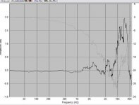
Here's the gated measurement, (i left it at default by speakerworkshop )
the driver is the pioneer full ranger b20 in a box
my measurements aren't that consistent yet, but I can see many with the peaks in the same region as the graph showned below
melt solder onto speaker wire,
place onto solder point and used tip to melt, I held on for a bit for it to melt and released
don't know if that's enough to kill the capsule, I don't know what's the more easier/faster way to do it.
Here's the gated measurement, (i left it at default by speakerworkshop )
the driver is the pioneer full ranger b20 in a box
my measurements aren't that consistent yet, but I can see many with the peaks in the same region as the graph showned below
Attachments
sqlkev said:This is what I did:
melt solder onto speaker wire,
place onto solder point and used tip to melt, I held on for a bit for it to melt and released
don't know if that's enough to kill the capsule, I don't know what's the more easier/faster way to do it.
Here's the gated measurement, (i left it at default by speakerworkshop )
the driver is the pioneer full ranger b20 in a box
my measurements aren't that consistent yet, but I can see many with the peaks in the same region as the graph showned below
Your image didn't come out clearly, but it looks as if your amplitude scale is only 0.6dB per division. Try resetting this to something like 5dB per division to give a more realistic idea of what you're seeing.
You can do this by right clicking the chart, selecting chart properties, selecting Y axis, and set the major grid to 5 and select it's check block. You may also have to adjust the min and max levels, as they default to "auto". Once you get a chart you like, you can right click it again and select "set chart as default", and it will stay that way on future measurements.
Sorry about the first image , me 
What about the second image?
Does it look alrite?
I tried to convert the .txt file to .frd, but that somehow won't work. It stills shows up as a .txt file, (bateman.frd.txt)
What about the second image?
Does it look alrite?
I tried to convert the .txt file to .frd, but that somehow won't work. It stills shows up as a .txt file, (bateman.frd.txt)
I somehow posted my last response before your last response????
Anyway, your 2nd graph doesn't look too bad...a 3dB rise in the top octave.
As far as the file name, just dowload the original file...bateman.txt.
Then rename (right click, select rename) it to bateman.frd.
Then open your SW project select RESOURCE/IMPORT, and browse to bateman.frd. This should import the cal file into your project directory.
Then go through the OPTIONS/CALIBRATE routine I mentioned earlier.
The only thing is, I've never tried to do this AFTER making the measurement. It's usually the FIRST thing I do. So it may not have any effect on measurements made previously.
as jbateman said change the range on the y axis, you are getting a very distorted graph there. 3db is roughly what the peak is on the Wallin measurements for the WM61a so I think you are probably seeing pretty normal data.
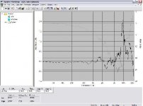
with the gating you need to open up the pulse response and find the first reflection and move the upper limit of time to before this reflection.
I've attached an example pulse response graph, I reset the y axis to -200 min +200 max.... the defaults of -32K +32K with the gain of my mike at 1M is way off. I've set the gate to about 6ms but it is possible that the first reflection here is actually around 4.5ms, It will be very diffifcult to get anything higher than 6 - 8 ms before a reflection in any normal room.
Tony.
Attachments
Does the Linkwitz mod get rid of the hump above 10,000 Hz?
Or is the hump still there, Linkwitz mod or no Linkwitz mod?
Or is the hump still there, Linkwitz mod or no Linkwitz mod?
Hi Keltic,
I doubt that the linkwitz mod would do anthing to the bump (unless the bump is due to the mic being overloaded with too high an SPL). The linkwitz mod is to allow the mic to handle higher spl levels.
My experience with it is that with my wallin preamp II the gain is much lower when the linkwitz mod has been made, the other thing is I had to reverse the polarity (ie use the ground as signal) or I got really bad distortion.
Tony.
wintermute said:Hi Keltic,
I doubt that the linkwitz mod would do anthing to the bump (unless the bump is due to the mic being overloaded with too high an SPL). The linkwitz mod is to allow the mic to handle higher spl levels.
My experience with it is that with my wallin preamp II the gain is much lower when the linkwitz mod has been made, the other thing is I had to reverse the polarity (ie use the ground as signal) or I got really bad distortion.
Tony.
Hello all,
Well, you are right, the Linkwitz modification wiil have absolutely no sffect on the FR of the WM61A and it is only allow the mic to handle higher spl levels, which is a MUST if you want to use this capsule for RTA measurements above 90-92db.
I'm using the Linkwitz modified WM-61A with DIY premp (using 2 OPA-627BP set for 10db gain each) on the SpectraPLUS RTA (on a laptop with an Audigy2 ZS Notebook PCMCIA soundcard) for setting up EQ's on PA systems and it's working beautifull.
I have compared it thought with a friend's 1/3 Octave hardware analyzer (costing some 3500$) and the results are identical.
Today I did some FR tests for the Aurum Cantus G2si (on ETF 5.0)and after loading the generic calibration files the results were very close to the published, maximum daviation 0.4db at 14.3Khz.
Regards
Padel
- Status
- Not open for further replies.
- Home
- Loudspeakers
- Multi-Way
- wm-61a topend peak- calibration? or resolder??