What hookup method do you suggest - fuse then capacitor followed by a voltage divider? Analyzer input impedance is 50 ohms.
Thanks
Charles
Thanks
Charles
None of the above!
You must be isolated from the mains.
Try a toroid transformer. Toroids have decent frequency response, smaller is usually better. Perhaps a 10VA totroid with a 6V secondary? Turns ratio and how the winding is made up will effect the bandwidth, but you can count on at least a few hundred kHz, and spikes at higher frequencies will still be visible on an FFT.
Charles,
Look at Elliott Sound Products - project 139 or 139a. You will find information on obtaining a signal with a current transformer that will isolate your measurement equipment from line voltages and current. You need a safe way to access mains voltage when connecting test equipment. A little searching on the usual internet sites will turn up good current transformers (commercial products with specifications). The devices in Project 139a are inexpensive and easy to obtain as well if you want to monitor AC voltage and current.
Look at Elliott Sound Products - project 139 or 139a. You will find information on obtaining a signal with a current transformer that will isolate your measurement equipment from line voltages and current. You need a safe way to access mains voltage when connecting test equipment. A little searching on the usual internet sites will turn up good current transformers (commercial products with specifications). The devices in Project 139a are inexpensive and easy to obtain as well if you want to monitor AC voltage and current.
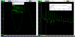
Charles, I got one of these:
Handyscope TP450 | USB Oscilloscopes | TiePie - USB oscilloscopes, spectrum analyzers, data loggers, multimeters, Arbitrary Waveform Generators
Can't build against that!
Jan
Handyscope TP450 | USB Oscilloscopes | TiePie - USB oscilloscopes, spectrum analyzers, data loggers, multimeters, Arbitrary Waveform Generators
Can't build against that!
Jan
Attachments
Last edited:
None of the above!
You must be isolated from the mains.
Try a toroid transformer. Toroids have decent frequency response, smaller is usually better. Perhaps a 10VA totroid with a 6V secondary? Turns ratio and how the winding is made up will effect the bandwidth, but you can count on at least a few hundred kHz, and spikes at higher frequencies will still be visible on an FFT.
And you need a voltage divider on its output with 50 output impedance and a low enough voltage not to blow your SA front end away - 0dBm is plenty(*), 0.25Vrms.
Note that your voltage divider has 50 ohms of the SA and your 50 ohm divider resistor in parallel, so for instance:
10Vrms -> 0.25Vrms uses 1k:50R divider, seeing 1k : 25R in reality
(*) even if the SA can take a higher input, it will start to distort itself at some point, 0dB is usually below that threshold.
What frequency range do you want to examine? Lowish frequency harmonics caused by rectifiers or non-linear loads, medium frequency disturbances, or VHF perturbations caused by PLC for example?What hookup method do you suggest - fuse then capacitor followed by a voltage divider? Analyzer input impedance is 50 ohms.
The answer will be very different, and any solution encompassing the whole range will be very limited regarding dynamic range and SNR.
Anyway, direct connection to the mains is never an option, even with a capacitor
Jan, that's a pretty nice mains voltage monitor.
Good to show what the local mains is like before and after anyone turns on their behemoth audio amplifier with its mains rectified power supply.
It has dc coupling and so appears to be usable across rectified secondary and B+ supplies when kept within the 450V working limit. And the frequency response is not too shabby, even for the base model's 25kHz max span, so should also be a nice tool for measuring ripple voltage attenuation through valve amp filtering stages.
It can also indicate what high frequency attenuation of mains noise can be gained when using an isolation transformer.
- Home
- Design & Build
- Equipment & Tools
- wish to monitor mains voltage with a spectrum analyzer