The point of a grid stopper resistor is to remove all external capacitance from being connected directly to the grid. And that is why one end of the grid stopper resistor is connected right up at the socket grid pin.
A reverse biased diode does have a very small capacitance.
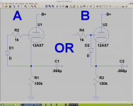
Schematic A is the correct way.
However, be sure to check what the worst case voltage and rise time of that voltage is that will be applied to the Anode of the diode. That diode has to pass that transient on to R1, C1, and whatever load C1 drives.
Remember that capacitors are dead shorts until they are charged.
That goes for C1. It also goes for what usually drives R2 (a coupling cap from the plate load of the previous stage, and that plate load is often connected to B+).
A reverse biased diode does have a very small capacitance.
Schematic A is the correct way.
However, be sure to check what the worst case voltage and rise time of that voltage is that will be applied to the Anode of the diode. That diode has to pass that transient on to R1, C1, and whatever load C1 drives.
Remember that capacitors are dead shorts until they are charged.
That goes for C1. It also goes for what usually drives R2 (a coupling cap from the plate load of the previous stage, and that plate load is often connected to B+).
Last edited:
- Status
- Not open for further replies.