Folks,
I have an Avel Y23 30VA 12V transformer here and I am planning on finishing a small Raspberry based music server for my home audio.
I also have all the other parts, and am close to finishing it all, but I noticed one thing about the transformer wiring diagrams that I need some clarification on.
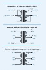
This transformer has dual primaries and dual secondaries (matched at 12V each). Because of this there are a handful of ways you can wire it, and it appears that there are two that are viable for my purposes.
First, I need two outputs One goes to the On/Off switch LED through a regulator module at 12V and the other will be converted and stepped down to 5.1 volts to go to the Raspberry.
For these, I'm using good quality voltage regulator modules. One can be adjusted for output voltage, and the other is fixed at 12V. I can use 12V AC output into both just fine.
So, I have two wiring options:
The Avel literature shows Option #1 with both primaries and secondaries wired in parallel, and it results in a 12v output at 2xI the amperage of the coils.
Option #3 in their diagram is the primaries in series, and the secondaries independent, with 12v output at the rated amperage.
Obviously, I can take the first and split and go to the two voltage regulators, but with Option #3, I have two circuits coming from the transformer that are possibly more independent.
My question is: Is there a reason to do one wiring option over the other? I'm going for low noise in the power supply to the Raspberry, so I thought it would be better to use Option #3, but I don't know that to be the case.
Any thoughts from the experts here?
Thanks,
---Michael
I have an Avel Y23 30VA 12V transformer here and I am planning on finishing a small Raspberry based music server for my home audio.
I also have all the other parts, and am close to finishing it all, but I noticed one thing about the transformer wiring diagrams that I need some clarification on.
This transformer has dual primaries and dual secondaries (matched at 12V each). Because of this there are a handful of ways you can wire it, and it appears that there are two that are viable for my purposes.
First, I need two outputs One goes to the On/Off switch LED through a regulator module at 12V and the other will be converted and stepped down to 5.1 volts to go to the Raspberry.
For these, I'm using good quality voltage regulator modules. One can be adjusted for output voltage, and the other is fixed at 12V. I can use 12V AC output into both just fine.
So, I have two wiring options:
The Avel literature shows Option #1 with both primaries and secondaries wired in parallel, and it results in a 12v output at 2xI the amperage of the coils.
Option #3 in their diagram is the primaries in series, and the secondaries independent, with 12v output at the rated amperage.
Obviously, I can take the first and split and go to the two voltage regulators, but with Option #3, I have two circuits coming from the transformer that are possibly more independent.
My question is: Is there a reason to do one wiring option over the other? I'm going for low noise in the power supply to the Raspberry, so I thought it would be better to use Option #3, but I don't know that to be the case.
Any thoughts from the experts here?
Thanks,
---Michael
Attachments
Last edited:
Hi, question 1 is - what is your house voltage? The primary can be prallelled as in pic 1 if you live in a 110v country. Othervise it should be in series. Then live with what the transformer can deliver.
Regards
Regards
If one secondary winding can supply sufficient current for the hungriest load I'd go for independance
Normally in 120v countries, you connect the primaries in parallel. If 240v, you connect them in series. That's really the only options. There is no "advantage" to be gained either way.
On the secondary side you can build a center tapped +/- supply with a single bridge or do the same with two separate bridges and no centertap. Personally I see no advantage to the dual bridge although some like it better. Of course with a unipolar supply, series or parallel determines the voltage and current you end up with but of course the VA or wattage available remains the same.
The only weird configuration I have seen is using these transformers for small tube preamps. You use one primary as the primary. The second primary as your HV winding, and the secondaries for the filaments. Pretty clever IMO! Just watch your current draw.
IMPORTANT: When putting windings in parallel, either primary or secondary, be sure they are phased properly. They typically show the phasing as dots on the winding ends. If you wire them mis-phased you can burn out the transformer almost instantly.
Last edited:
I am surprised that you need 12V to power an LED, but you certainly don't need a 15VA winding. An LED consumes something less than 20mA. Your 12V regulator will dissipate more power than the LED. Parallel the secondaries, rectify and filter, then tap off to the 12V reg and to the low voltage regulator, which will use the most current. The 12V regulator should not be a significant source of noise upstream.
Thanks for the comments everyone...
I figured out that the literature is missing the supply voltage on the bottom diagram. It will not deliver 12V wired that way unless you have 230V supply, so as u/Gusser mentioned, that is really not an option to maintain the voltage I need on the secondary side. This actually makes sense if you go through the wiring and coil ratios, but when I saw the option on the diagram, I figured it may be viable.
As to the load on this, neither of them are large loads at all. The LED is probably only a watt, but it does require 12V. The Raspberry is only 15 watts or so with add-on boards, so it is pretty small as well. The transformer could be smaller, but this was about the smallest I could find easily, so I went with it.
i figured if I had a spare, I could dedicate one winding to the LED and the other to the Raspberry, but they are now wired together in parallel in the transformer, so i split off after that and took a branch to each of the regulator modules.
I have it all wired and am getting a solid 12v DC for the power light, and 5.1v DC for the Raspberry. I'll test it for a while to see what happens when it heats up to see if I need to adjust the voltage to the Raspberry at all. Not sure what its specs are for under/over voltage.
All that is left now is to mill some holes and mount the various input/output jack extenders to the back of the box, get the pieces arranged in the box and get the final wire routing completed. I'm still waiting on a micro SD slot extender and then I can lay out the back panel.
I'm excited to try it with a clearly much better power supply than a cheap switch mode power supply. I can hear an audible 60hz hum coming from the board of the Raspberry when plugged in to the cheap wall wart. I don't expect to hear that at all with this power supply.
---Michael
Build and use a Mains Bulb Tester.
It will prevent damage to your transformer at first Power ON, even if you get the wiring completely wrong.
It will prevent damage to your transformer at first Power ON, even if you get the wiring completely wrong.
A dual primary rated for 115Vac can be used as a paralleled primary for mains supplies from 110Vac to 120Vac (nominal). The maximum range from the mains is much wider than that.
You can for initial testing/measurment use just one 115Vac primary connected to the 110/120Vac mains. It works and has no risk in getting the primary wiring incorrectly connected. It will reduce the capability to 50% of maximum but that is not an issue initially. Avoiding blowing up your transformer is the much bigger issue.
But the other Primary will have the same voltage as from the mains. You must separately insulate those two spare tappings. And insulate all the secondaries by fitting each tapping into separate terminals of an insulated terminal block. This allows you to take measurmeents safely and make connections for further assembly of the PSU.
Last edited:
As to the load on this, neither of them are large loads at all. The LED is probably only a watt, but it does require 12V.
I don't want to be pedantic, but a typical LED has a voltage drop of about 2V or less, and is rated to consume about 20mA (though for comfortable brightness in a darkened room less than 10mA is better), so that means less than 40mW, far less than a Watt. Now the power switch assembly probably includes a dropping resistor designed for a 12V supply, on the assumption that most projects have a 12V supply available or it is easy to add, and they are right, but the power consumption of the whole circuit including the current limiting resistor would still be below 1/4W. So again, dedicating half your transformer's current capacity to a single LED is a waste.
The Raspberry is only 15 watts or so with add-on boards, so it is pretty small as well.
15W is not "small" and is the bulk of the demand on the PSU. I would not use a transformer much smaller than what you have, just for that.
Pay attention to Andrew's suggestions. Build a simple dim bulb tester, and use insulated terminal blocks for all connections both on primary and secondary side.
Oh, and good luck and happy building!🙂
Now there is something that I have never considered. That really is clever.The only weird configuration I have seen is using these transformers for small tube preamps. You use one primary as the primary. The second primary as your HV winding, and the secondaries for the filaments. Pretty clever IMO! Just watch your current draw.
- Status
- Not open for further replies.
- Home
- Amplifiers
- Power Supplies
- Wiring dual coil transformer for best performance