Hi friends!
When you‘re working with shielded/coax wires, which usually have quite some strands (…), how do you connect them to the connector/solder-lug?
Most of the times the shields sums up to 1-2 mm² or even more. Do you cut part of the strands?
When you‘re working with shielded/coax wires, which usually have quite some strands (…), how do you connect them to the connector/solder-lug?
Most of the times the shields sums up to 1-2 mm² or even more. Do you cut part of the strands?
I use fluorocarbon insulated shielded cable, which makes it much easier to deal with in terms of soldering. I expose about 1-1.25" of the outer shield braid, and trim it back to about 1/4". I strip out some 24 AWG teflon insulated stranded wire (gray or black) to an inch or two, then wrap the stripped portion of the wire around the braid and solder it in place. I then insulate this connection with an inch or two of appropriate diameter heat shrink. That gives me my ground termination. I then strip about 1/4" of the center conductor, twist it with some 24 AWG stranded teflon wire of a different color, solder, then fold it back along the shrink tube-insulated ground connection. I slide another appropriately-sized piece of heat shrink over the folded-back center wire, and shrink it with a heat gun to get a center conductor connection with some strain relief. This results in a cable with color-coded center conductor and ground connections. It's a bit tedious, but that's how I do it.
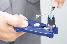
Slide a Hellerman sleeve over the cable.
Form the screen to fit back over the insulation, wrap a length of tinned copper single strand 24/28gauge wire in a loop around it and solder it to make a good connection. Send the new screen wire alongside the other wires, insulate and solder to the required terminal.
Pull the sleeve over the new screen connection.

So I seem to have gotten it right: make a sort of "reduction" for the screen/shield...
Thanks to both of you!
Thanks to both of you!
So the coax shield becomes the ground wire? I thought the shield isn't supposed to carry any current. (Sorry if I'm misunderstanding what's going on here.)
You still have to ground the shield or it won't shield at all... The shield current should flow to some ground and not pollute the signal wires. That might be chassis ground or signal ground.
For coax the shield carries the signal ground current internally and the RF / noise currents externally, which is why dense braid or ribbon performs better than loose braid or lapped, as the noise currents are kept on the outside to a greater extent (Faraday cage).
For coax the shield carries the signal ground current internally and the RF / noise currents externally, which is why dense braid or ribbon performs better than loose braid or lapped, as the noise currents are kept on the outside to a greater extent (Faraday cage).
I may of course have been messing around with the terminology, as I did not spend attention to its function but on how to connect it.
Sloppy I know!
Sloppy I know!
Just so I'm certain... You're connecting the shield at both ends, so your (single conductor) coax is effectively a two conductor cable. Is that right?
Well, yes, in my case it's a Mogami 2520 (single conductor) for a single-ended wiring, the shield being the return. (I I was to use a shielded 2-conductor cable, as the 2549, I'd use the shield as shield, connected at only one gnd...)
My question basically was about how to deal with the diameter of the shield (when twisted to a stranded wire). Do I cut off a part of the shield? Do I use another piece of wire to connect the shield? This sort of things...
Your question suggests this isn't really good practice, doesn't it? What's all about a single-core coax in audio then? ( <-- ahem)
Thank you, @myleftear. The answer to your original question was also helpful, and sorry if I diverted the thread. But your answer to my question was also super helpful and much appreciated. For some reason, I was under the impression that using the shield as a conductor was bad practice, but you make a good point. Also, isn't a coax with BNC connectors doing this same thing?
Surprised to see them still in production. I installed thousands in the Nineties but haven't seen one in decades.Hellerman sleeve
Attachments

This was not my idea. I copied it from Ampex(?).Hi friends!
When you‘re working with shielded/coax wires, which usually have quite some strands (…), how do you connect them to the connector/solder-lug?
Most of the times the shields sums up to 1-2 mm² or even more. Do you cut part of the strands?
What I do is separate the braid wires about 1/2 inch from the end. Thread the
center conductor out of the hole you made in the shield. Put a piece of of hookup
wire (stripped of course) in the hole in the braid where the center conductor was.
Solder the hookup wire to the braid. Clip the excess length and place a piece of
heatshrink over the braid. You now have 2 leads from your coax that are easy to
handle.
G²
Normally when a coax cable is used as an interconnect, the shield is connected at both ends and is the most important part of the interconnect.
It has three tasks:
1] the signal return leg.
2] a shield
3] a low impedance path to reduce Common Impedance Coupling Noise.
* * * * * * * *
But sometimes inside a unit, the shield is only connected at the source end. The idea is to reduce power supply noise pick-up.
It has three tasks:
1] the signal return leg.
2] a shield
3] a low impedance path to reduce Common Impedance Coupling Noise.
* * * * * * * *
But sometimes inside a unit, the shield is only connected at the source end. The idea is to reduce power supply noise pick-up.
When you‘re working with shielded/coax wires, which usually have quite some strands (…), how do you connect them to the connector/solder-lug?
what connector?
I've come across several connectors: Most often it's just the PCB (where the GND-lug seldom is big enough for the shields full diameter), then, there's the classic RCA, male and female. These aren't too challenging, as they usually provide enough space for qqquite some diameters. Then, I am using the lemo 00 (Nim-Camac) for my gear, that's where it starts to get finicky, and the most challenging job was connecting a Gotham GAC-1 to a SME 3009 connector. (It was more a mental challenge than a technical one, as the tonearm is on a TD-125 subchassis, thus the cable had to "float in the air" and allow the subchassis' movement…)
- Home
- Design & Build
- Construction Tips
- Wiring, cables: How do you cope with the shield?