Hi
I came across a old RS power transformer, nice chunk of iron.
I tough that I could use it with a SE 6V6 or similar and 6SL7 as a pre.
This choice of valves because thats what I got laying around.
The specs on the power tranny are.
250 V @ 80mA
250 V @ 80mA
Screen
6.3 V @ 3A
6.3 V @ 3A
C.T V @ 3A
Now in my little acknowledge in respect to transformers a question arrived prompt, (knowing that the the filament wiring for this kind of valves its 3.15 V), can I still use this PT for the 6V6 and 6SL7 ?
I cant figure out how.
The other problem is that, regarding the secondary 80mA HT is that per rail or total?
So total will 80mA only and x 2 rails will be 160 mA.
Is this thinking correct?
Thanks
The following is based on the data in your post.
If the secondary HV windings are separate, you can put them in series to give 500VCT @ 80mA. Or you can put them in parallel to give you 250VAC @ 160mA. If you put them in parallel, you will need to use a full-wave bridge rectifier unless each 250VAC winding is center-tapped.
You will need to mind polarity on the windings to do this - the phasing of the output voltages is important.
The 6.3V windings, if separate, could be used to power the 6V6 output stage heaters separately from the 6SL7 preamp heaters.
Do you have a complete part number? Somebody here might have a datasheet handy...
Good luck.😎
~ Sam
Hi
Thanks for your input.
Theres no part number, its a old British made Radio Spares trasformer.
The HV windings are 250-screen- 250.
The filament is 6.3-CT-6.3
...so I need to wire the output valve using 6.3V to pin 2 and the CT wire to pin 7 and do the same with the preamp and leave the other 6.3V from the PT wire unconnected?
Cheers
Hi
Thanks for your input.
Theres no part number, its a old British made Radio Spares trasformer.
The HV windings are 250-screen- 250.
The filament is 6.3-CT-6.3
...so I need to wire the output valve using 6.3V to pin 2 and the CT wire to pin 7 and do the same with the preamp and leave the other 6.3V from the PT wire unconnected?
Cheers
Well, all I can say is that sorting out an old power transformer when you have it sitting on the bench in front of you is one thing. Doing it from afar over the internets is something else...
Best advice I can offer is that you should probably just get your meter and carefully measure the output voltages from this transformer. It shouldn't be that difficult, just be very careful - the voltages can be lethal. Follow the standard precautions when measuring high voltage - there is a sticky on this at the top of the Tube/Valve page.
The tube heaters use 6.3VAC. You may measure aslightly higher voltage on the transformer, that is not unusual. The unloaded transformer voltage will always be somewhat higher than when you hook up a load (the heaters).
Same with the HV winding. The voltage you measure will be higher with the transformer unloaded.
Good luck, practice safe meter measurement techniques, and I hope you find it a useable transformer for your project.
😎
Many thanks rfengineer2013.
Its a NOS so those are the voltages written on it.
Thanks once again really appreciated.
Its a NOS so those are the voltages written on it.
Thanks once again really appreciated.
Post a photograph, showing the labelling. It would be unusual for an RS item not to carry the RS part number.
Your description suggests to me that you have a 250V 80mA, and 6.3V 3A secondaries, each centre-tapped. Enough for a small radio receiver or a guitar practice amp.
Your description suggests to me that you have a 250V 80mA, and 6.3V 3A secondaries, each centre-tapped. Enough for a small radio receiver or a guitar practice amp.
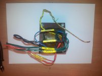
You seem to have a 250V 75mA secondary (reds), and a 6.3V 3A secondary (greens) with a CT (black). There is also an interwinding screen (blue). I don't know what the yellows are (primary?).
So you need a bridge rectifier for the 250V. Depending on how the transformer is specified you might get 75mA DC or just 25mA. My guess is 75mA, as that would better match the available heater current. The transformer is probably about 75VA in total.
So reds go to a rectifier bridge. Greens go to heaters. CT is grounded somewhere in the PSU (or can be elevated to reduce hum, but probably not needed in a guitar amp). Screen is grounded to the chassis.
You might have about 50mA for a Class A output stage, so maybe 5W output.
Thanks.
Yeah yellows are primary.
That its fine may be for a 6V6 style amp I was hoping to do a dif. project 2 x ecl82 and 2 x 12AX7.
Someone mention that I could probably use and I quote ''you can put them in parallel to give you 250VAC @ 160mA'.....how does that going.
Cheers
Yeah yellows are primary.
That its fine may be for a 6V6 style amp I was hoping to do a dif. project 2 x ecl82 and 2 x 12AX7.
Someone mention that I could probably use and I quote ''you can put them in parallel to give you 250VAC @ 160mA'.....how does that going.
Cheers
No. That was assuming that you had two 250V secondaries, which your original post seemed to imply. You have one 250V secondary. 75mA is enough for one output stage (such as 6V6 or EL84) with some voltage amplifiers in front, or maybe two lower current stages with less extras. You might, just, get away with a low power push-pull.
apologies for the confusion...but if you look at the picture you'l see 250V sec x 2 I think someone called it full wave TX...I'm not too clear on this
That is clear now thanks.
I guess I got to find a different TX for my ECL82 project.
What about wiring the Fil.
A ecc83 takes 6.3V pins 4 & 5 and CT pin 9 and 6V6 takes also 6.3v pin 2 and CT to pin 7 (I believe) ... so how can I wire this 2 valves using 6.3V-CT-6.3V
Thanks
I guess I got to find a different TX for my ECL82 project.
What about wiring the Fil.
A ecc83 takes 6.3V pins 4 & 5 and CT pin 9 and 6V6 takes also 6.3v pin 2 and CT to pin 7 (I believe) ... so how can I wire this 2 valves using 6.3V-CT-6.3V
Thanks
Forget it.Someone mention that I could probably use and I quote ''you can put them in parallel to give you 250VAC @ 160mA'.....how does that going.
That suggestion was based on your poor verbal description hinting at 2 250V secondaries , while you only have one.
EDIT:
Same confusing description as before.so how can I wire this 2 valves using 6.3V-CT-6.3V
You have *one* center tapped 6.3V secondary.
Last edited:
- Status
- Not open for further replies.
- Home
- Amplifiers
- Tubes / Valves
- Wiring a power transformer