Hi All,
I am trying to get some info for a friend, on how to wire a Twin Triode in
a SE 6AS7G Tube Power amplifier. We want to try and wire the tube as Push
Pull in which the two Plates inside will push pull to gain more power and cancel
out the distortion levels! Could that be like Trying to wire a twin triode tube
in Ultra-linear mode? Is this possible to get the Single twin triode power tube to
Behave as if two tubes were used in Push pull output stage? Has anyone ever
tried this? If so, would not the Voltage have to be higher in order to get the current
up to a higher level? Any thoughts would be appreciated! Lydia
Last edited:
Just wire it up as if it were two separate Triodes, which is what it is. They just happen to share a common heater element.
It will be a a triode PP amp.
Here is an example using 6N6P:
http://www.pastisch.se/faktiskt/amp87.gif
And here is an actual 6AS7 one:
Data of 6080pp Stereo Amp.
It will be a a triode PP amp.
Here is an example using 6N6P:
http://www.pastisch.se/faktiskt/amp87.gif
And here is an actual 6AS7 one:
Data of 6080pp Stereo Amp.
Last edited:
One may not get very very high channel separation by this method, often one side can "hear" the other. Otoh this can be a good thing in some cases. Easy to test - just play one channel, dummy load, listen out the other with no input.
_-_-bear
_-_-bear
When the Bear Speaks People should Listen!!!
One may not get very very high channel separation by this method, often one side can "hear" the other. Otoh this can be a good thing in some cases. Easy to test - just play one channel, dummy load, listen out the other with no input.
_-_-bear
Wiring each tube (both elements in one tube) as one channel will stop any cross-talk issues.
Also note,the 6AS7/6080 (basically the same tube) will require a pretty good voltage swing on the grid,as it doesn't have much 'gain'.
Also note,the 6AS7/6080 (basically the same tube) will require a pretty good voltage swing on the grid,as it doesn't have much 'gain'.
I can see that being a problem with SE amps where channel separation would matter, but if both triodes in one tube are used in push-pull, how would this matter?
oh, yeah, hmmmm... ok well actually it might have an effect as a form of negative feedback! hey! a new invention!! 😀
_-_-
_-_-
It should not matter
My thought is that Distortion, would decrease and the signal is sent thru one
side to the other and It should be exactly the same as if one were to use this
as a Push Pull Pair for each channel. I would imagine the distortion to be around
2.8% in full 6-8 watts output pere channel as most of the 2nd Harmonic distortion will be gone. The 6AS7G should be stabilized. It could not hurt to have an Adj. Fixed Bias regulator for biasing these type of tubes in Output stages. Hopefully, We would end up with a 6AS7G SE PP Class A tube amplifier.
I think Stability is Key here. If Noise or crosstalk is involved it should be canceled out in this Push Pull wiring, True? Any thoughts............. Lydia
I can see that being a problem with SE amps where channel separation would matter, but if both triodes in one tube are used in push-pull, how would this matter?
My thought is that Distortion, would decrease and the signal is sent thru one
side to the other and It should be exactly the same as if one were to use this
as a Push Pull Pair for each channel. I would imagine the distortion to be around
2.8% in full 6-8 watts output pere channel as most of the 2nd Harmonic distortion will be gone. The 6AS7G should be stabilized. It could not hurt to have an Adj. Fixed Bias regulator for biasing these type of tubes in Output stages. Hopefully, We would end up with a 6AS7G SE PP Class A tube amplifier.
I think Stability is Key here. If Noise or crosstalk is involved it should be canceled out in this Push Pull wiring, True? Any thoughts............. Lydia
A KISS exemple:
Push Pull 6AS7
Note the "stacked" PSUs:
+400V for the "SRPP-paraphase-splitter-driver" wich provide the huge grid swing the 6AS7's need.
+200V for the power stage itself.
Delivers up to 8W at les than 1% distortion for some 100W total consumption 🙂
Have fun
Yves.
Push Pull 6AS7
Note the "stacked" PSUs:
+400V for the "SRPP-paraphase-splitter-driver" wich provide the huge grid swing the 6AS7's need.
+200V for the power stage itself.
Delivers up to 8W at les than 1% distortion for some 100W total consumption 🙂
Have fun
Yves.
Cross talk between the two triodes in these is a non-issue. Very low internal resistance, only a few pF of capacitance, and extremely low mu, all means cross talk will be next to nill.
These make great little PP amps, the low rp means the OT can be low impedance, which means relatively few turns and much smaller parasitic inductance and capacitance in the OT.
The only difficult thing with them is the low mu, aim for +-100V drive for the grids. (Actually not that difficult, the low gain gives low miller capacitance which makes them easy to drive)
b+ around 200V, grids at negative 80-90volts is a good starting point.
The only difficult thing with them is the low mu, aim for +-100V drive for the grids. (Actually not that difficult, the low gain gives low miller capacitance which makes them easy to drive)
b+ around 200V, grids at negative 80-90volts is a good starting point.
You don't need +/-100V drive.
150V/60 mA at about -65V bias is a very good compromise for this tube. Primary load 2K-to-2.5K plate-to-plate for PP or 1.4-1.5K for SE. You only need a driver capable of +/- 70V swing. Positive grid drive is not recommended. In my experience it is better to stay below 10W plate dissipation (for each section) in order to achieve some useful life.
I run mine at 100V 100mA which has 30V (B+ of 130V) across the cathode resistor. This then only requires 30V of drive for full output and the grids are relatively easy to drive at this bias point. Very reliable and a much fuller sound than run at lower currents and higher voltages.
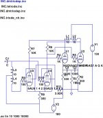
The triodes are very variable between sides so simply tying the cathodes together is a recipe for disaster.
As for bias arrangement, what is shown below works, though LM317 CCS at 100mA work better in place of the 330R;
The triodes are very variable between sides so simply tying the cathodes together is a recipe for disaster.
As for bias arrangement, what is shown below works, though LM317 CCS at 100mA work better in place of the 330R;
Attachments
Last edited:
Various.
I have used 15VA toroidal's, but only with a step down of 6:1+1. I think any step down of 3:1+1 or above would work.
I have also used the OEP input transformers and the Z3003E is a good candidate for small money. I have also used a microphone line driving transformer from OEP with a 9:1+1 ratio - worked fine.
I have also had success with the encapsulated Talema toroidals as input phase splitting chokes. They work fine in this role, but the interwinding capacitance is just to high if configured as an input transformer, even with a step down ratio. My guess is that just about any toroidal transformer will make an excellent high performance input phase splitting choke.
Of course the secret of success is having a low source impedence, and for that I have used a toroidal step down transformer at the output of my preamp - that thing could just about drive the speakers directly.
PS, that circuit was never built as shown so is only there for reference to the output bias arrangement. However the circuit design approach has been used in my current amp of two years standing.
Shoog
Last edited:
You don't need +/-100V drive.
150V/60 mA at about -65V bias is a very good compromise for this tube. Primary load 2K-to-2.5K plate-to-plate for PP or 1.4-1.5K for SE. You only need a driver capable of +/- 70V swing. Positive grid drive is not recommended. In my experience it is better to stay below 10W plate dissipation (for each section) in order to achieve some useful life.
Yes agree, these tubes work great on lower voltages as well. I've used them with a 75V rail and high current and they really sound great. So with lower plate voltages naturally the drive voltages can be lower. My current amp has 200V on plates and about -80V on grids. I've had 210V and -95, but prefer the lower values. 40ohm cathode resistors and panel meters for monitoring ensures safe operation. I use one triode section in each tube, two of those in parallel, each triode running at 15watts. As Shoog mentioned the two triodes are poorly matched, easier to find two triodes in seperate envelopes that are similar. It seems triodes on pins 123 are more similar to triodes on same pins on other tubes than they are with the triode on pins 456. Have been running the same tubes like that for many years, no sign of over loading. As long as the total temp is within limits, a lonely triode section can handle at least 15watts.
Last edited:
I think its best to use CCS biasing to ensure that everything stays happy. This makes the inevitable triode mismatch in a single envelope immaterial. I have run mine this way for years without incident and everythings stays tickety boo until a point when they go into oscillations.
Shoog
Shoog
Mismatch can be overcome just using a transfomer with some gap to allow DC inbalance. Otherwise one could use a fixed bias.
Actually it could be back bias which doesn't require a dedicated supply. One just moves the cathode resistor in another position and decouples the filtering for each output tube. Using a resistance value a bit higher than needed leaves some room for adjustment. Note that the back bias resistor will experience the total current drawn from that PSU secondary. It can be regarded as a midway solution between a true fixed bias and self bias.
An historical example is the Brook 12A:
http://www.diyaudio.com/forums/tubes-valves/164434-brook-12a-clone.html
- Status
- Not open for further replies.
- Home
- Amplifiers
- Tubes / Valves
- Wiring a 6AS7G to be Push Pull within its own envelope