I just finished putting my project into a case and I thought I should share my experience.
I came to need this kind of player after I’ve finished my BLH speakers. They went into a new location in the living room, because they were big, and there’s no easy way of transmitting the music from my computer to them. Cables were out of the question, so I started looking around for solutions.
Since I’m using a Mac, I decided to go for AirPlay. But I have no AppleTV (nor do I want one) so I had to do with a custom job.
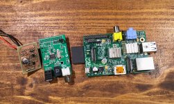
Here’s where Raspberry Pi came in very handy.
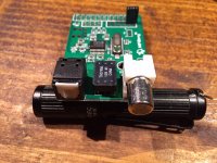
But Raspberry Pi has a PWM circuit instead of an audio card so I had to look for output options. Since I have my mini2496 DAC I decided to throw it into the mix so the only thing I needed was a digital output shield for the Pi.
I settled on the Digi shield from Hifiberry guys. Great little board! Mine came without an output transformer and I sourced one just because it could be installed and the isolation comes in handy. They only have a few boards in stock left and they save the OTs for the new boards (for RPI v2). Forgot to mention that I’m using a Raspberry Pi B (1st gen).
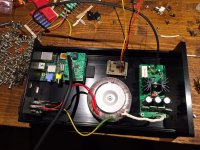
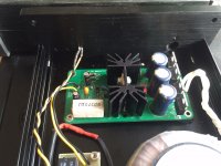
I used a regulated linear power supply since I had a few boards already from an earlier project.
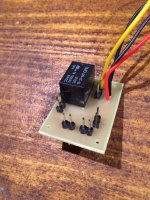
To control the thing, I needed an interface since there’s no buttons on the Pi.
I found this article that explains very good how to make your own setup:
Adding a Switch Raspberry Pi Geek
There’s a schematic, code for the Pi and it’s not complicated at all.
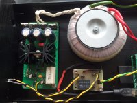
Besides the relay, I’ve used smd parts so I have a tight setup. Worked first go, no drama.
There’s an On button, Soft-Off button, Hard-Off button and one LED connection (also power input/output).
For a transformer I used a 7VAC/3A one, I had it made locally.
First I connected everything and started to test the software.
The OS I used is Raspbian, and the AirPlay emulation software is called “shairport-sync”:
https://www.raspbian.org/
https://github.com/mikebrady/shairport-sync (great guy Mike!)
Also I’d suggest you make a full backup of the SD card after you’re happy with the OS setup. Might came in handy if the card gets corrupted from various reasons. This stuff happens more than often on the Raspberry Pi. I suggest this method, worked for me:
https://smittytone.wordpress.com/2013/09/06/back-up-a-raspberry-pi-sd-card-using-a-mac/
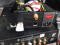
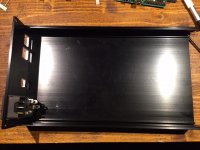
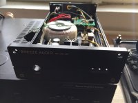
Now seeing that everything is working great I wanted to install the whole thing into a case.
After some measurements, I decided on an aluminium case from ebay. You can find the exact case if you search ebay for “1506DAC”. Mine came out at about 46$ with shipping. Pretty good.
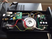
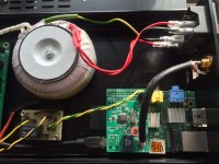
To be able to use the raspberry pi into this case, I asked the seller if he could cut the back plate to my specs, and he agreed. I made a quick sketch in SketchUp and sent the file. I messed the measurements on vertical by 2mm but it fits perfect anyway (I left some room for error in measurements).
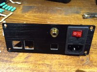
I made cutouts for the Ethernet port and USB port, also for RCA and Toslink socket.
I unsoldered the RCA and Toslink connectors from the Digi shield so I can route the signal to the back plate (and also because the Digi board does not fit as the RCA extends a bit).
I think the worst part of this project was making the holes for the spacers, and threading them. I messed one tap, it broke into the hole. Good thing the case is symmetric, as i rotated it and started again on the other side 🙂
One could also cut the side of the case in order to use the HDMI connector of the Pi. I don’t need it.
The last thing I need to do to this case is add the buttons. It came only with the button cover, no mechanism. Also you need non-locking/contact buttons (don’t know the technical term). And I’m thinking of using one for On, and one for Soft-Off, don’t need the Hard-Off one.
The On button can be installed in the larger hole, and the off button I’m thinking of installing in one of the 3mm led holes. Two of them are free at the moment, I just hope I could find a 3mm wide button, with about 6-7mm length.
This setup also allows me to add a parametric eq for the sound. It completely transformed the sound of the speakers, to the point where I no longer need a subwoofer for the Dallas II BLH.
I used Arta with a measurement mic to get the response, then I corrected manually until I found a very good response that sounds great!
I then used a virtual sound card software to capture all the sounds from my computer, then route them to the parametric EQ, then send them via AirPlay to the Raspberry Pi.
Works like a charm, and I’m completely wireless now 🙂
I added some pictures from the project.
If you are interested, I can add the project files from the Raspberry Pi control pcb. I had a mishap with it, as I had some small passings for ground that got interrupted during production. So I added a wire to link the two ground planes together. The board could have come out better but I rushed it and didn’t care much.
This setup can be expanded to use a NAS for stored music, but I don’t have such a thing. Maybe in the future.
For AirPlay stuff, the software is limited to 16/44.1 but I don’t care that much, it sounds great! For network files, it can go to 24/192 afaik.
I came to need this kind of player after I’ve finished my BLH speakers. They went into a new location in the living room, because they were big, and there’s no easy way of transmitting the music from my computer to them. Cables were out of the question, so I started looking around for solutions.
Since I’m using a Mac, I decided to go for AirPlay. But I have no AppleTV (nor do I want one) so I had to do with a custom job.
Here’s where Raspberry Pi came in very handy.
But Raspberry Pi has a PWM circuit instead of an audio card so I had to look for output options. Since I have my mini2496 DAC I decided to throw it into the mix so the only thing I needed was a digital output shield for the Pi.
I settled on the Digi shield from Hifiberry guys. Great little board! Mine came without an output transformer and I sourced one just because it could be installed and the isolation comes in handy. They only have a few boards in stock left and they save the OTs for the new boards (for RPI v2). Forgot to mention that I’m using a Raspberry Pi B (1st gen).
I used a regulated linear power supply since I had a few boards already from an earlier project.
To control the thing, I needed an interface since there’s no buttons on the Pi.
I found this article that explains very good how to make your own setup:
Adding a Switch Raspberry Pi Geek
There’s a schematic, code for the Pi and it’s not complicated at all.
Besides the relay, I’ve used smd parts so I have a tight setup. Worked first go, no drama.
There’s an On button, Soft-Off button, Hard-Off button and one LED connection (also power input/output).
For a transformer I used a 7VAC/3A one, I had it made locally.
First I connected everything and started to test the software.
The OS I used is Raspbian, and the AirPlay emulation software is called “shairport-sync”:
https://www.raspbian.org/
https://github.com/mikebrady/shairport-sync (great guy Mike!)
Also I’d suggest you make a full backup of the SD card after you’re happy with the OS setup. Might came in handy if the card gets corrupted from various reasons. This stuff happens more than often on the Raspberry Pi. I suggest this method, worked for me:
https://smittytone.wordpress.com/2013/09/06/back-up-a-raspberry-pi-sd-card-using-a-mac/
Now seeing that everything is working great I wanted to install the whole thing into a case.
After some measurements, I decided on an aluminium case from ebay. You can find the exact case if you search ebay for “1506DAC”. Mine came out at about 46$ with shipping. Pretty good.
To be able to use the raspberry pi into this case, I asked the seller if he could cut the back plate to my specs, and he agreed. I made a quick sketch in SketchUp and sent the file. I messed the measurements on vertical by 2mm but it fits perfect anyway (I left some room for error in measurements).
I made cutouts for the Ethernet port and USB port, also for RCA and Toslink socket.
I unsoldered the RCA and Toslink connectors from the Digi shield so I can route the signal to the back plate (and also because the Digi board does not fit as the RCA extends a bit).
I think the worst part of this project was making the holes for the spacers, and threading them. I messed one tap, it broke into the hole. Good thing the case is symmetric, as i rotated it and started again on the other side 🙂
One could also cut the side of the case in order to use the HDMI connector of the Pi. I don’t need it.
The last thing I need to do to this case is add the buttons. It came only with the button cover, no mechanism. Also you need non-locking/contact buttons (don’t know the technical term). And I’m thinking of using one for On, and one for Soft-Off, don’t need the Hard-Off one.
The On button can be installed in the larger hole, and the off button I’m thinking of installing in one of the 3mm led holes. Two of them are free at the moment, I just hope I could find a 3mm wide button, with about 6-7mm length.
This setup also allows me to add a parametric eq for the sound. It completely transformed the sound of the speakers, to the point where I no longer need a subwoofer for the Dallas II BLH.
I used Arta with a measurement mic to get the response, then I corrected manually until I found a very good response that sounds great!
I then used a virtual sound card software to capture all the sounds from my computer, then route them to the parametric EQ, then send them via AirPlay to the Raspberry Pi.
Works like a charm, and I’m completely wireless now 🙂
I added some pictures from the project.
If you are interested, I can add the project files from the Raspberry Pi control pcb. I had a mishap with it, as I had some small passings for ground that got interrupted during production. So I added a wire to link the two ground planes together. The board could have come out better but I rushed it and didn’t care much.
This setup can be expanded to use a NAS for stored music, but I don’t have such a thing. Maybe in the future.
For AirPlay stuff, the software is limited to 16/44.1 but I don’t care that much, it sounds great! For network files, it can go to 24/192 afaik.
Attachments
-
 FullSizeRender.jpg560.2 KB · Views: 205
 -
 IMG_4117.jpg453.9 KB · Views: 99
 -
 IMG_4113.jpg485 KB · Views: 89
 -
 IMG_4112.jpg435.2 KB · Views: 96
 -
 IMG_4099.jpg589.7 KB · Views: 89
 -
 IMG_4098.jpg498.3 KB · Views: 87
 -
 IMG_4096.jpg367.1 KB · Views: 185
 -
 IMG_4097.jpg452.1 KB · Views: 189
 -
 IMG_4095.jpg567 KB · Views: 204
 -
 IMG_4094.jpg527.3 KB · Views: 204
Still need to ground the case, and also install the toslink connector. In my stupidity I ordered a receiver, not transmitter.
I don't need it really, and mini2496 doesn't have a receiving connector (I have one now), but maybe I will put one in the future.
So far I have the output transformer and that's good enough.
The power socket comes without a fuse, I installed a 160mA one as I had it in my box. I will get a 100mA one that's more appropriate for that transformer.
Attachments
I've been doing some similar things with the Raspberry Pi 2:
I use the ubiquitous 5V 2A switching power supply for the Pi and just leave it running all the time because it uses only about 1W of power. I stream audio over my WiFi network to the clients (have multiple clients) using open source software and am able to sync multiple clients.
I recently gave a talk that includes some of this stuff that you can watch on youtube at this link:
https://www.youtube.com/watch?v=SB7IPqdt0UE
I really think that streaming audio plus DSP on the Raspberry Pi is an exciting new DIY frontier and it's nice to see others doing this kind of thing. My approach doesn't require any fabrication or custom circuits so people might find that easier. I'm also currently investigating ways for the Raspberry Pi to accept analog audio or spdif signal as input so it can be connected locally to other audio equipment (e.g. not obtaining the audio via the network) if that is desired.
- streaming audio client
- DSP in software on the Pi that implements a multiway loudspeaker crossover
- USB DACs for audio output like this one, or this one
I use the ubiquitous 5V 2A switching power supply for the Pi and just leave it running all the time because it uses only about 1W of power. I stream audio over my WiFi network to the clients (have multiple clients) using open source software and am able to sync multiple clients.
I recently gave a talk that includes some of this stuff that you can watch on youtube at this link:
https://www.youtube.com/watch?v=SB7IPqdt0UE
I really think that streaming audio plus DSP on the Raspberry Pi is an exciting new DIY frontier and it's nice to see others doing this kind of thing. My approach doesn't require any fabrication or custom circuits so people might find that easier. I'm also currently investigating ways for the Raspberry Pi to accept analog audio or spdif signal as input so it can be connected locally to other audio equipment (e.g. not obtaining the audio via the network) if that is desired.
A great thing would be a parametric EQ on the RPi. If I stream something from my phone, I loose the EQ.
Also, I think the chip that is used on my shield has a digital input as well but I don't swear on it. I think there's another toslink unpopulated pad on the shield, and after measuring it's not linked to the one that's populated (only Vcc/GND), signal is not, so might be an input.
The chip used on this shield is WM8804G, have a look at the datasheet, maybe it features input as well.
I thought of going with a case for the RPi/Digi board as I've seen for this combo but I like the idea of a regulated linear supply, and I had one laying around.
Also I find the USB connector to not be so solid and in time it might get damaged. Plus the lack of controls for the RPi, I like to turn it off whenever possible.
Thanks for the links, I'll look into them.
As hardware becomes cheaper and has more processing power, I really think that this platform is very good for DSP. Nowadays you can customise your RPi with a few options for larger quantities.
All that's needed is software support for it. There are a few great projects in the works as far as I know.
This link shows you how, and my LADSPA plugins (link in my signature) give you the tools, to do whatever DSP signal processing you want with the Raspberry Pi. This includes as many EQ bands as you want.
I found that the miniSTREAMER from miniDSP is plug and play compatible with the R-Pi under Raspbian. This has SPDIF input and output at up to 24/96 for only $35.
I found that the miniSTREAMER from miniDSP is plug and play compatible with the R-Pi under Raspbian. This has SPDIF input and output at up to 24/96 for only $35.
I don't know how the USB is implemented in RPi 2, but in 1st gen it's a mess. If you have a higher data transfer on network, it craps out.
That's why I went for i2s to spdif solution.
And I really think that you need a decent DAC for decent sound quality. I don't trust those small usb ones. Also I'm not suggesting going all in but something better than those usb ones for sure. I think the option of having a digital output on the raspberry is a very powerful one, and also allows for various DACs as flexibility.
That's for home use. For commercial uses I suspect a compact do-it-all adapter is more preferable. I've seen people happy with the RPi DAC, might want to look into that as well.
Something like this:
https://www.hifiberry.com/dacplus
But I've seen clones cheaper if interested.
I'm watching your presentation for now, and I'll look into the plugins you showed.
Does the 1st gen have the power to support those?
DSP in software...
- DSP in software on the Pi that implements a multiway loudspeaker crossover
USB and the ethernet interface are all on the same bus, at least from what I have been told. It's capable of about 60MB/sec IIRC in total, theoretical max.
I have used a USB WiFi input and two stereo USB DACs as output at 48kHz and I never once experienced a problem (dropout, etc.) with a R-Pi 2. I don't have any experience with earlier models so I can't comment on that.
You are welcome to spend your money as you would like. The USB DACs that have use the ES9023 DAC, which is more than fine in my opinion so I don't yearn for something that is "more" in any way.
I used a Scarlett 2i4 usb soundcard on the RPi 1st gen, and with a usb wifi dongle I'd have some crackles on the output.
The crackling was worse if I tried to download something on the RPi, with network load it would become worse.
I'm using the official wi-fi dongle for the RPi, and the soundcard is pretty nice.
Maybe they are doing better management in the 2nd gen.
Do make tests with this. Think of someone trying to download some large music files, or the RPi is streaming from a local NAS, some hi-def files.
For the DAC, the chip isn't everything. Implementation matters, power supply etc. But I think the final point is the target application as I've mentioned.
If you want to have a home system you would care as how the device has been built. For commercial applications I guess the 10$ ones can do the job.
Looking at your presentation I didn't understand something, maybe you could clarify.
NTP (Network Time Protocol) is used for clock synchronisation between computers.
Since RPi doesn't have a battery it looses time and it's needed in some applications.
I don't understand how that syncs the packets between different RPis. As far as I know, this protocol syncs the universal time, not the CPU clock. Or maybe is there something I don't know?
Looking at your presentation I didn't understand something, maybe you could clarify.
NTP (Network Time Protocol) is used for clock synchronisation between computers.
Since RPi doesn't have a battery it looses time and it's needed in some applications.
I don't understand how that syncs the packets between different RPis. As far as I know, this protocol syncs the universal time, not the CPU clock. Or maybe is there something I don't know?
I have at least three computers involved when I play audio. The server (not a Raspberry Pi) is playing the music/file/stream. Instead of "playing" it to a local analog output via a DAC it streams it on the network. There are two loudspeakers (left and right). Each speaker has a Raspberry Pi in it or at it, so two Raspberry Pis. These need to playback the audio together at the same time.
Any computer has an internal timekeeping device, typically working off of an internal pulse generator like a crystal. The crystal has a target frequency, e.g. X MHz or whatever, which is not perfectly accurate. So between any two devices running a clock that keeps time there will be some slight inaccuracy. This is larger than you might think, so two units can drift apart as much as a couple of seconds per hour. If you are playing music any at the start the sound is in sync at the end of 1 hour the sound will be coming out of one speaker 1 second after the same sound comes out of the other speaker.
From what I understand NTP adjusts something about the OS software that sets how "fast" the timekeeping clock is running. It tries to bring the local clock on to the same rate, and the same time, as "real time" as obtained from an NTP time server (e.g. on the web, etc.). Typically the best NTP time servers use very accurate clocks, GPS, etc. to provide their reference for time. In fact you can set up the Raspberry Pi to gets its time from a GPS unit that has a PPS (pulse per second) output, and it will then be a very accurate time reference.
Anyway, getting back to my application... I need to have both Raspberry Pi clients very closely sync'd so that they playback the audio stream at the exact same time. Of course "exact" is just a matter of the time scale you are talking about, and for audio I have found that when the difference in playback time is on the order of 500 microseconds or less of each other this is sufficiently synchronized. My approach is to have the audio server act as a local NTP server, and then have the Raspberry Pi clients get their time info from it.
It turns out that the longer you leave NTP running, the better it performs. It might take hours to settle down after startup, so I just leave everything powered up all the time. My server uses a 35W power supply, and the R-Pis only use about 1W of power, so this is no big deal. EVery once and a while there is some glitch (like when my wife accidentally turns off the power to one of the Pis) and I can tell when I start playing audio. I just SSH to the Pi and manually synchronize the time to the audio server and all is well afterwards.
I got a message from the guy who develops shairport-sync and he said that my efforts with NTP were similar to what his code does. Since I like development work, I typically don't use black box software or pre-packaged OS builds. I think that I get very good time control using my NTP method, and I can improve that at will by implementing a local Stratum 1 server with a GPS time reference.
Ok, didn't know this.
I thought that NTP was used for the system clock/date only. Didn't know it affects the internal clock of the system (as in the CPU clock).
Just finished seeing your presentation and I will have a look into the plugins.
At the moment I could only use the EQ side of things as my main speakers use a fullrange driver. But I'd like to see what's what for future use.
I'm using one RPi as I don't need more, but it I plan on adding another one in the bedroom for it's sound system.
You said there's a delay of about 1 second between the source and speakers. Do you plan to work on that? Can it be reduced?
For music this is not really a problem, but for watching movies the problem becomes obvious instantly.
AirPlay manages to sync with the speakers by pausing the video until it caches up. But still, the EQ chain I use does again add to the delay. I can only watch movies via AirPlay by removing the EQ.
Good stuff, keep up the good work!
The plugins are still useful for your speaker - even though you don't need highpass and lowpass functions you can still use EQ and shelving filters to shape the frequency response of the full range driver.
The 1 second delay comes about from all the different buffering that is used in my system. There are a lot of different steps along the way between the player on the server and the DAC output on the R-Pi and each one typically has a buffer of 100-300 msec. I simply need to reduce these as much as possible and then do some extended listening to see if the audio stream suffers any dropouts, etc.
I know that some software (e.g. VLC player) allow for video to be delayed like you mention. I don't watch movies, only listen to audio, so I haven't experimented with this personally.
This is wonderful!
Thank you for all your work!
b
This link shows you how, and my LADSPA plugins (link in my signature) give you the tools, to do whatever DSP signal processing you want with the Raspberry Pi. This includes as many EQ bands as you want.
I found that the miniSTREAMER from miniDSP is plug and play compatible with the R-Pi under Raspbian. This has SPDIF input and output at up to 24/96 for only $35.
Thank you for all your work!
b
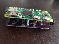
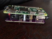
Here's a smaller version of a wireless DAC using the new Raspberry Pi Zero.
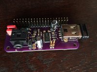
This board I designed myself, using the various info available out there. I shamelessly used the same pins as the other commercially available options like DAC+ of Hifiberry and IQ DAC of IQaudIO.
For some reasons I couldn't get the board to work with the Hifiberry driver, but it worked a treat with the IQ one.
I think it has something to do with the fact that I used a PCM5142 instead of a PCM5122 chip.
Nevertheless it sounds great! The nice USB hack also allows me to use the wifi dongle without the adapter and this way I get a smaller outline of the whole package.
Soldering the tssop and 0805 packages by hand was a bit of a trouble but turned out ok.
Also has an option of external power for the DAC. The usb is continuously powered by the Pi. There's a jumper that can select between external and Pi0 power. The aux power goes into the unpopulated holes next to the jumper.
Attachments
Last edited:
- Status
- Not open for further replies.
- Home
- Source & Line
- Digital Source
- Wireless player with Raspberry Pi +mini2496 DAC