Yes you need both capacitors, just in case there is a short circuit in the cable. Theoretically you can run the power in the same cable, just make sure there are no connectors where any standard device can be plugged in, causing damage.
No need for two capacitors. If C2 is not there ans the cable has a short, T2 will switch on with no sound, nothing else will happen.
C1 is sufficient. I would use an electrolytic for reliability. There is no need to waste your money with expensively over priced capacitors.
C1 is sufficient. I would use an electrolytic for reliability. There is no need to waste your money with expensively over priced capacitors.
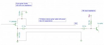
3nF for 10m of cable? sounds wrong to me - I'd expect more like 1nF as 100pF/m is very
common ballpark value for screened cables.
common ballpark value for screened cables.
use 2 caps, you never know what someone will try and plug into the receiving end. I would also put a 10-20K ohm resistor after the first cap and before the second cap. If you use an electrolytic the resistors will keep the caps from becoming reversed bias. I dont know, from the limited schematic what the DC values are at each end.
You show no gate bias on the 2N5458. I don't think you can find a 2N5458 which will self-bias high enough to pass the specified 3V (rms?) input; anyway THD is non-zero and not controlled in design or use.
Biasing to around half-way is normally a good plan. For both the JFET and the BJT. Which means they can be direct-coupled, NO cap between.
I do not see what you gain by putting a BJT in the end. Build all your electronics in front, then the reception is just a power/signal split. Now no DC on the signal lead of the cable.
I stole your 82uFd cap value but unless you are feeding total crap DC supply it can be smaller. But in electrolytic, not TOO small: well-oversized e-caps have very low distortion (see D.Self and others). 10uFd feeding a assumed 100K load is 0.2Hz, 500X bigger than absolutely needed, thus flaws are 500X less. (Remember most modern guitar amps and stage mixers are choc-a-block with little e-caps.)
I do think 3nF is a lot of C for ordinary cable.
Attachments
Thanks guys
Impressive PRR and your photoshop skill
I've checked the cable its 3nf until I found out that I have joined the hot and cold pin from end to end , i've cut cold pin, and yeah 100pf/m. OMG ive record song many clients using that cable.
82uf bcoz that fet only consume 4.56mA x 18v =82mw "then rule of thumb somewhere" =82uf? or nah?
- Home
- Source & Line
- Analog Line Level
- Wire before Caps out