jcx: It's not that bad really. A 10K/300 transformer used with a low rp/high gain tube such as a 6E5P will have an output impedance under 50R (DCR being taken into consideration). In practice, even the edcor pcw10k-7k/300-32, which has highish DCR, is not making things very bad. I've compared a amp with it and a 6e5p against a Gilmore dynalo and they're very hard to pick apart once matched in volume.
In the amp I'm rebuilding, it's even better than that since I'll be using a near 0r output (µfollower with mosfet). Obviously, I don't need a transformer with stellar spec in this particular case but I'd like to have a versatile transformer which can be used in quite a few configurations.
edit: cross-posted with dsavitsk 😛

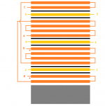
The dielectric constant of paper is lower than mylar. The dielectric effects the coupling capacitance in the transformer. This effects the high frequency response. Less is better.
I can't comment on which stack up is better as I don't have enough experience yet.
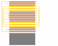
I did wind one transformer with parallel secondary's, and a second with series secondary's and was not able to measure nor hear any difference between the two transformers.
I can't comment on which stack up is better as I don't have enough experience yet.
I did wind one transformer with parallel secondary's, and a second with series secondary's and was not able to measure nor hear any difference between the two transformers.
Last edited:
the specification of signal xfmr in pri/sec impedance is from literal "impedance matching" applications - zero reflection, maximum power transfer
to avoid ambiguity, aid design and analysis it is better to use turns ratio, magnetizing L, DCR, k factor/leakage L, SRF...
to avoid ambiguity, aid design and analysis it is better to use turns ratio, magnetizing L, DCR, k factor/leakage L, SRF...
- Status
- Not open for further replies.