Hi,
Merry Xmas to all! 🙂
Will this circuit work? I drew it about a month ago, and would like any sugestions/comments before I start building it. The switching freq is around 250kHz. I'm planning on using a LM319 for the comparator and TL082CP for the osc.
Sorry for the badly drawn schem.
Thanx alot
Regards,
Werner
Attachments
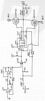
well it would work. But the sound qualtiy would be POOR, also there would be some power loss due to the lack of a dead time circuit. You need a resistor and a diode before the mosfet stage to prevent both being on at the same time.
What is the chip in there as i can read it from the schematic.
You could also use some feedback from the output stage back to the comparitor as it would prevent the destortion of the mosfets.
The inductance is a bit high for a 250k switching frequency, should be more like 60uH. The capacitor value is also a bit low.
But with some adjustments the circuit is a worker.
Rob
Sorry but it won't work at all.
You need level shifting between the output of your comparator, that swings between 0 and +6V (or -6V and +6V if you use an opamp), and the input of the IR2111, whose supply should be referred to -56V.
You can find lots of similar schematics in the forum, one of them for example in the "help! turn on big current" or similar. It doesn't work correctly yet but you can find how to connect the level shifter(s).
If you need it for full-range, you have to lower the inductance of the filter to, say, 20-40uH.
yes that is true i didnt spot voltage level, You need a voltage amplifier in there to alow an ouput of more than +-6V. I suggest a biased transitor/ mosfet voltage amplifier amplifier.
Sorry, bob, but that's not what he needs.
He needs a voltage level shifter. It can be solved with a single PNP transistor and a couple of resistors.
Best regards
He needs a voltage level shifter. It can be solved with a single PNP transistor and a couple of resistors.
Best regards
Hi Werner,
Give LTspice a try, it's free, do the tutorials it comes with/read the help section get the basics of it figured out and then try a few ultra simple circuits of your own in it... within no time at all you'll be able to let your imagination run wild with it, much better than pencil and paper.
Best,
Chris
Hi, Thanx
Sorry, forgot to draw the diode infront of the mosfets, the ones in parallel with the gate resistors.
As for the level shifter, I now have a circuit, that uses a PNP transistor, I took that part from some old ClassD car amp, which used the IR2011 or something like that.
I'll be working more on the circuit, as soon as I have FORMATTED my machine, for a strange reason my XP64 is getting slower than my grannies 700MHz Celeron! 😕
Thanx alot,
Cheers,
Werner
- Status
- Not open for further replies.
- Home
- Amplifiers
- Class D
- Will This Work?