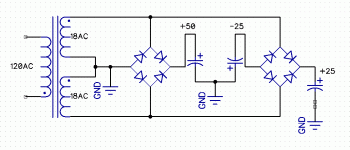
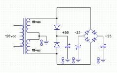
First bridge is SHORTING the transformer on negative cycles.
And its positive peaks will only reach 25V, not 50.
And its positive peaks will only reach 25V, not 50.
Taking the first pair of diodes, this is just a 25V supply using half wave rectification on each transformer half.
Typically what is done using valve rectifier in tube equipment.
Do the 2 supplied items share a common ground?
If not, connect the 50V item to -25v & +25V terminals.
Typically what is done using valve rectifier in tube equipment.
Do the 2 supplied items share a common ground?
If not, connect the 50V item to -25v & +25V terminals.
I see it now... darn it. Yes, they would both share a common ground.
I'm building a hybrid tube amp (EL34's) with OPA2134 inputs. I need
*/-15vdc for the OP's and +30v to the tubes. I was trying to get a work
around to get all that from the one transformer. What I'll probably do is
a resistor/divider off the secondary B+ (290v) and use a Zener to get
the +30.
Thanks for your help!
Mike
You mention -/+25V and +50V in post #1 but then mention -/+15 and +30.
If the latter are the final regulated supplies you want to end up with and if the current requirement of the +30V line is low then it should be possible to generate that from a cap/diode multiplier.
If so then you might get some ideas in post #3 here
Generating an auxilliary negative rail from DC rails
If anything, worry/solve thehighvoltage high power supply; lowering that to feed a couple Op Amps is easy.
To clarify... I am going to use the +/-25 into 7815 regulators to get the +/-15 needed to run the OP's. The +30 goes to pin 5 on each pair of EL34's through 100ohm resistors. I'm not sure of the current necessary to function properly. This amp uses approx. 535vdc to the primary center tap of the audio xformer and is then divided down to 290vdc at pin 4 of each EL34 pair through 470ohm resistors.
> The +30 goes to pin 5 on each pair of EL34's
G1 of EL34 ought to be a zero-current load. 1mA in a divider from B+ would be ample.
I hope you have not confused the polarity of this voltage (it is usually negative).
G1 of EL34 ought to be a zero-current load. 1mA in a divider from B+ would be ample.
I hope you have not confused the polarity of this voltage (it is usually negative).
WHAT??????? 😱To clarify... I am going to use the +/-25 into 7815 regulators to get the +/-15 needed to run the OP's. The +30 goes to pin 5 on each pair of EL34's through 100ohm resistors. I'm not sure of the current necessary to function properly. This amp uses approx. 535vdc to the primary center tap of the audio xformer and is then divided down to 290vdc at pin 4 of each EL34 pair through 470ohm resistors.
Not sure what you want to do but you look no clue to me, sorry.
Had a hint of that from your first questions but now we are getting into dangerous territory.
290V DC across a 470 ohm resistor dissipates 180W !!! 😱
And you would at least have two of them inside your chassis ... if not four.
PLEASE post the FULL schematic of what you are trying to build, maybe we could help you with it.
Actually, I've been an electronics tech for over 40 years and have built several Class A amps and high end AB amps. This, however, is my first tube amp.
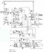
As you can see in the attached schematic, it is +30 to pin 5 of each EL34.
It's a hybrid and I only attached the part of this amp I plan to build Thanks to everyone for their help so far... you have all probably forgotten more than I know about building tube amps.
As you can see in the attached schematic, it is +30 to pin 5 of each EL34.
It's a hybrid and I only attached the part of this amp I plan to build Thanks to everyone for their help so far... you have all probably forgotten more than I know about building tube amps.
Attachments
One last thing... I'm using a power transformer that will produce around 535vdc for the plate voltage. Will I have to reduce the voltage to pin 4 as well? (To say, 240vdc?)
- Home
- Design & Build
- Construction Tips
- Will this work? (dual bridges - one transformer)


