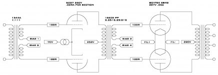
Nothing left but final assembly on the 26 pre so it is time to start thinking about the amp it will drive. I’m considering all transformer coupled diff 6CG7 driving 6b4Gs. Since the interstage I have is sensitive to dc imbalance I want to independently bias the grids of the driver stage through the split secondary of the input transformer. I will also do the same thing for the B4Gs
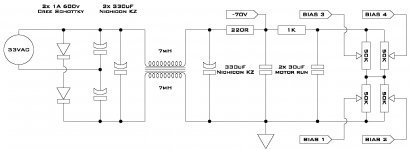
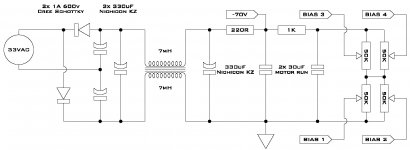
I would also like to use a depletion mode mosfet as a current sink on the tail to force ac balance. So I need a negative voltage for the bottom of the CCS and 2x -35 to -70V 2x -6 to -10v
Modeling the supply as positive with the mess of 50K pots at the end as a single 50K resistor I get 21mV ripple at the 70v tap and 701uV ripple at the bias resistor.
Thanks,
Marty
Attachments
Rapid answer: you'll run into troubles!
One of your 330uF is directly tied to AC ! Unless you're planning to have fireworks, I'll try to avoid that 😀
Other than that why use double choke ?
A simple one should be enough to my knowledge.
One of your 330uF is directly tied to AC ! Unless you're planning to have fireworks, I'll try to avoid that 😀
Other than that why use double choke ?
A simple one should be enough to my knowledge.
Thanks for the replies
Could someone please help me to understand what is wrong with the doubler circuit?
It is just a standard full wave doubler with the diodes flipped which I assumed I needed to do to get a negative voltage. I included the choke only to block any HF noise on the supply and used common mode because they are small and inexpensive.
Thanks again,
Marty
The lower lead from the 33VAC source is correct. The upper lead needs to go thru a diode to function. Check out the power supply for H-K Citation Two, reverse the diode and capacitor directions and you'll have what you think you have now.
Craig
Craig
Martyh yep it's better for the diodes
But for the choke, it looks like a choke to be used for main filtering.
Inductance looks like it has a too little value.
But for the choke, it looks like a choke to be used for main filtering.
Inductance looks like it has a too little value.
An easy way to figure out the Henries needed is to divide the load resistance by 1200. Example, 400 VDC@20ma. 400 divided by .02 is 20KOhms. 20K divided by 1200 is 16.66666666666666666666H. This mainly works for a constant load. Also if you notice the smaller the load the more Henries needed.
Craig
Craig
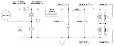
Thank you both again. Here is a new version with diodes in the correct place and a bleeder to make sure there is enough current through the choke. I also omitted an rc filter section as the big choke really quiets things down in psud.
I get 253uV ripple at the -80 and 1.5uV ripple in the bias stack which I guess should be more than quiet enough.
I get 253uV ripple at the -80 and 1.5uV ripple in the bias stack which I guess should be more than quiet enough.
Attachments
- Status
- Not open for further replies.
- Home
- Amplifiers
- Tubes / Valves
- Will this supply work?