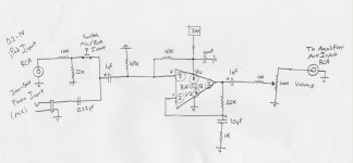
i want to plug my computer and or ipod into the preamp and it will increase the volume to the same line level of a cd player or dvd player's audio out which can be plugged into my stereo. without a preamp with my amp and my computer up all way the sound is not even that loud. ( i got the opamp BA15218 from a broken stereo it seems the be similar to the ne5532) i attached a picture of the circuit
Attachments
No, it doesn't look like it will work.
Overall there's attenuation on the iPod input of 33dB and the opamp gain is 27dB. So the best it can do is make your iPod half as loud as when its not in circuit. Your input 1uF is the wrong way around and your output pot seems redundant (as well as seemingly connected backwards). The 1uF output coupling cap would do well it be more like 100uF. The 27dB gain will probably prove inadequate for a mic input.
Overall there's attenuation on the iPod input of 33dB and the opamp gain is 27dB. So the best it can do is make your iPod half as loud as when its not in circuit. Your input 1uF is the wrong way around and your output pot seems redundant (as well as seemingly connected backwards). The 1uF output coupling cap would do well it be more like 100uF. The 27dB gain will probably prove inadequate for a mic input.

Its definitely an improvement🙂
I'm a bit dubious about your initial premises - you say your computer doesn't go loud enough - but sound cards put out similar levels to CD players (1-2VRMS) in my experience.
On to your revised circuit - why the input attenuator then opamp gain? Why not reduce the attenuation (like have no attenuation) then have reduced opamp gain? Loss then gain is just a recipe for increased noise and distortion, it gives no advantages. I'd suggest having the volume control on the input, not the output. Your coupling caps (0.22uF, 1uF) still look rather too low. But its coming along...😛
You should probably read this, or other tutorials on designing with opamps:
HeadWize - Project: Designing an Opamp Headphone Amplifier (A HeadWize Design Series Paper)
HeadWize - Project: Designing an Opamp Headphone Amplifier (A HeadWize Design Series Paper)
No, remove R1 and R2 and replace them with the volume pot, wiper to C1. Reverse polarity on C1 and increase its value to 1uF. Reduce 22k to 4k7, reduce 10k on output to 100R, increase 1uF to 100uF and put +ve to left. Add a resistor of 100k where the volume pot used to be. That oughta do it.
I was talking about the new 100uF output coupling capacitor - connect its +ve terminal to the opamp output (the left side of the cap on the schematic). Currently you don't show polarisation on that cap, perhaps because its only 1uF.
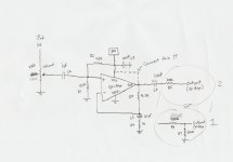

Yeah, it looks good without the dotted connection between output and Vcc, and with output network #1.
Hi Mjf,
the bass response of the pre-amp (post11) is compromised.
It is limited by the input filter and it is also limited by the feedback filter.
I try to get the pre-amp to pass at least half an octave wider and preferably one octave wider at both the low end and the high end than the power amp that follows.
If the power amp is +0,-1dB from 3Hz to 100kHz then I aim for pre-amp +0,-1dB from <=1.5Hz to >=200kHz.
You will find many pre-amps that exceed this minimum specification by a large margin.
I would also add an RF filter to the input of the pre-amp.
Last edited:
hello andrew.
...........yes,this is a "compromise schematic", in development. i tried to use many of the parts from the circuit in post 10. cheap parts and simple.
greetings
...........yes,this is a "compromise schematic", in development. i tried to use many of the parts from the circuit in post 10. cheap parts and simple.
greetings
modified again
You people always complain about the sound of capacitors and then go out of your way to install as many as possible. Use dual balanced supplies and eliminate most of the caps AND get rid of turn on transients (thumps).
G²
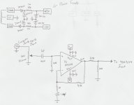
24Vac+24Vac is too high for a +-12Vdc opamp supply.
Change the two rectifying diodes to a diode bridge.
Will the opamps run from +-15V or +-18V or +-21V?
Choose a transformer Vac to equal the regulated DC output voltage, i.e. use 15+15Vac for +-15Vdc
The 4k7 & 1k0 define the gain as 4.7/1+1=5.7times=+15.1dB
The 4k7 on the output is far too high.
Try somewhere between 47r and 330r.
Hi,
the preamp will not destroy what follows it. The pre-amp cannot think.
The operator might destroy what follows.
the preamp will not destroy what follows it. The pre-amp cannot think.
The operator might destroy what follows.
- Status
- Not open for further replies.
- Home
- Amplifiers
- Chip Amps
- Will This Pre-Amp Circuit Work