You need the non inverting input biased correctly.
Follow the data sheet,
http://www.datasheetcatalog.org/datasheet/stmicroelectronics/1458.pdf
Follow the data sheet,
http://www.datasheetcatalog.org/datasheet/stmicroelectronics/1458.pdf
thank you for pointing that out, do you think the power-section that powers the TDA2030 will do good for the chip?
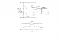
The power supply looks confusing. Currently you seem to regulate only your + rail to 9V, you would need another regulator for the - rail, 9V seems rather low for the chip.
Anyway, I would not regulate at all. Just make a dual polarity unregulated supply. The 2x12V AC output should give somewhere around +/-15 rails.
Anyway, I would not regulate at all. Just make a dual polarity unregulated supply. The 2x12V AC output should give somewhere around +/-15 rails.
There are a few issues.
First of all, the power supply is inadequate. The chip needs more voltage and more current to drive a speaker load (4 or 8 ohms). For instance, 8W RMS into 8 ohms needs already 1A RMS, which is 2.8A pk-to-pk more at higher powers and lower speaker impedance. The required voltage is 8 times that in 8 ohms. So you need at least 24 or 30V total supply like +/-12V or +/-15V.
The 7809 is inadequate here.
The series cap at the output is too small for good bass. If, for instance, you want your low freq cutoff (-3dB point) at say 30 Hz, the series cap should have an impedance at 30Hz equal to the speaker load. Worst case, this could be 4 ohms. The series cap impedance is: 1/(2*pi*f*C) which means for 30 Hz you need C = 1/(2*pi*4*30) = about 1200uF
You really should check the data sheet; it is specifically made to answer your questions.
jan didden
do you think the power-section that powers the TDA2030 will do good for the chip?
12Vac will give almost 12*1.414=17Vdc after rectification. Your cap is rated 16V so it must be of good quality to be able to handle the 17V. Replace the cap if possible.
With the 17V, a 7809 will need to drop 17-9=8V. That will be very hot.
Then why waste the power (or voltage)? 7809 regulator is not good sounding anyway so I can't see benefit from lowering the power. I prefer higher power with traditional filter. But yes, the IC must have better spec at lower power.
TDA2030 quality is very batch dependent. You can see from the minimum-typical-maximum THD spec. If you're lucky you will get 0.1% in listening level but most of the time you will get worse than that. A TDA2009 is better in that it can give 0.1% at around 3W consistently.
The Power supply that has the 7809 regulator will power the pre-amp. My concern is that, could I just use a transformer and 4 diodes to power the TDA2030 directly?
[snip] My concern is that, could I just use a transformer and 4 diodes to power the TDA2030 directly?
Yes of course but it all depends on the voltage the transformer gives off and the voltage and current rating of the diodes; they should be up to the task.
jan
The Power supply that has the 7809 regulator will power the pre-amp. My concern is that, could I just use a transformer and 4 diodes to power the TDA2030 directly?
I would use at least 4700uF in the power supply for decoupling and then ,as the datasheet suggests, 100uF electrolytic and 100nF film on the amlifier board. The 100nF caps should be as close to the chips power pins as possible. If you feel groovy, add a snubber to the PSU.
I think I have enough information so I will go ahead and build this thing. one thing though could a TDA20230 chip design be able to push a 410 or 412 cab?
No! Atleast not much louder than a clock radio. Those 410 and 412 cabs are typically driven by 50-500W solid state or tube amplifiers.
A TDA2030 will only be able to drive a set of bookshelf speakers to any significant volume.
A TDA2030 will only be able to drive a set of bookshelf speakers to any significant volume.
I think it depends on what you mean by significant volume. PA and Instrument speakers are considerably more efficient than typical bookshelf speakers. A 'quad' has no crossovers and uses four high-efficiency (large) speakers in series- parallel, so it will produce much more SPL than a bookshelf box with a tiny 130mm HT driver. There could be 10dB SPL difference and the load on the amplifier would be no greater. Load has little to do with the driver dimensions or the quantity.....A TDA2030 will only be able to drive a set of bookshelf speakers to any significant volume.
However, it seems vaustin89 actually wants a guitar amp and of course, the low power won't get even the cabs to wake up, let alone get pumping. The best use might be for a practice amp. using a good size baffle, single high efficiency guitar driver in an open-rear box. Cheap, loud and with just 5W chip amps.
- Status
- Not open for further replies.
- Home
- Amplifiers
- Solid State
- Will my design work?