I have a board using one -ve and one -ve reg (L7815/7915).
Supplied with +/- 25v both output correct voltages unloaded.
Trouble is as i add opamps in one by one into the circuit (they're the only thing using the +/-15v regulated power), at a certain point the voltage from the +ve reg drops to -0.8V. It is still seeing +25v from the preceding supply. It gets mildly warm with around 40mA being supplied to it. The -ve reg works just fine supplying -15v all the time.
It doesn't matter which opamps are added in (there are 10 in total) or where they are in the circuit. It's as if a threshold is reached and the +ve reg drops its output. It is nowhere near hot enough for a "thermal shutdown", and i have 100 ohm protection resistors in line with both at this stage.
I just don't get it, under what conditions does a regulator do this? can anyone shed some light??
Twin rail circuits often have problems where one starts before the other and pulls the other rail negative (or positive for the 7915). This then makes the load chips latch up and may cause the second regulator to malfunction.
The easy cure is reverse biased 1A Schottky diodes from the outputs to ground
The easy cure is reverse biased 1A Schottky diodes from the outputs to ground
What davidsrsb said. These chips have maximum in-out voltage specs. With a total of 50V between the two input rails this spec can be easily exceeded on start up. Add the diodes to stop the outputs being pulled the 'wrong' way.
Which 7805 / 7905 are you using. The L variant is only rated at 100mA, above this they will go into current limit and the output will drop to near ZERO.
Try changing them for M (500mA) or H (1A).
Try changing them for M (500mA) or H (1A).
Schematic?
Here is the schematic of the psu part of the board:
An externally hosted image should be here but it was not working when we last tested it.
Thanks very much for the insight here. I ordered some 1A shottky diodes and will try this tomorrow. I think this could be the root cause for a number of reasons:
1) It is quite unpredictable. Sometimes two opamps in circuit is enough to cause the problem. Other times up to 5 opamps is fine. So it doesn't seem to be directly linked to the load current.
2) the preceding +/-25v power supplies (they are independent for each rail) take a few seconds to reach rated output. I guess that gives ample time for one of the regs to turn on before the other, causing this latching issue.
I don't see exactly how one rail can be pulled to the other, i suppose that occurs via the load somehow?
I am using the L regulators (L7815/L7915). I thought they were rated 1A max not 100mA. I will try the schottky diodes first before switching regulators to possibly an M model.
This is actually a very interesting problem... and in all the years I have played around with regs I have never actually experienced the issue first hand although it is mentioned in some old data sheets and there is actually a reference to one of them here in the first link.
http://www.ece.vt.edu/tutorials/download/Preventing_Voltage_Regulator_Latch-up.pdf
http://www.ece.vt.edu/tutorials/download/Preventing_Voltage_Regulator_Latch-up.pdf
the led's after the reg is sucking all of the current
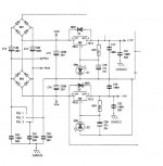
here is a schematic taken from a power supply from a mixer (irrelevant parts removed)
also a reversed biased diode across the regulator (1n4001 ) prevents drops
I also recommend increasing the cap before the regulator to 2200 uf @35V. everyone I've seen use about 10X more capacitance before the regulator.
and I've had brand new regulators fold over because they were defective.
Attachments
Last edited:
The diodes across the regulators in DavesNotHeres post protect against damage if the input is shorted.
The OP is a different problem, which has bitten me once 20 years ago. I think I used 1N5819s from the outputs to ground on a +/- 5V supply
If you use 317/337 regulators, they don't latch as they don't have a ground connection, but you still have issues with maximum input-output differential and possible destruction of load devices as they suffer temporary supply reversal.
If you use 317/337 regulators, they don't latch as they don't have a ground connection, but you still have issues with maximum input-output differential and possible destruction of load devices as they suffer temporary supply reversal.
Yes, that one has bitten me too with similar parts (LM333/350). Whether the problem occurs I think has a lot to do with the decoupling topology. If its mainly rail to ground then there's not normally a problem. But if there's a fair bit of capacitance rail-rail then it's much more likely to bite.
The schottky diodes have solved the problem (at least after a few test start ups). Thanks davidsrsb and others.
Before receiving them, i installed hard switches on the +/-25v inputs to look at how switch on timing affects operation. I found switching the 7815 (+ve reg) a fraction of a second before the 7915 results in correct start up on both rails. Seems the 7915 starts up a little quicker, latching the +ve rail and causing 7815 to misbehave.
Before receiving them, i installed hard switches on the +/-25v inputs to look at how switch on timing affects operation. I found switching the 7815 (+ve reg) a fraction of a second before the 7915 results in correct start up on both rails. Seems the 7915 starts up a little quicker, latching the +ve rail and causing 7815 to misbehave.
- Status
- Not open for further replies.
- Home
- Source & Line
- Analog Line Level
- why would +ve regulator output -ve voltage? ?