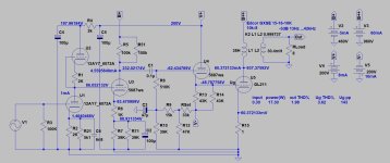
I clone the above in mono block. Recently the right mono block B+ shot above 1000V. As a result the tube was damaged. The B+ used be about 955V. My Left mono block is still working.
I would like to know the reasons for the B+ to shoot up. Thanks
Output tube draws about 60mA. I put in another tube, the heat produce was abnormal,so l quickly switch off.
Could it be one of the rectifier tubes, the voltage doubler capacitors or the 510K resistors?
Could it be one of the rectifier tubes, the voltage doubler capacitors or the 510K resistors?
What happened exactly? The tube was too hot? Did you measure the voltage at the plate at this moment? When did you measure the 1000V?
To me it sounds as if the negative bias voltage may be off, the tube will then pull much more current and dissipate more heat.
It goes without saying that troubleshooting this amp is very dangerous, do you know a technician able to do that?
To me it sounds as if the negative bias voltage may be off, the tube will then pull much more current and dissipate more heat.
It goes without saying that troubleshooting this amp is very dangerous, do you know a technician able to do that?
And, voltage will go up if there is no load... If the tube is installed and working well, the current drawn will cause voltage drop due to resistance in the power supply. If you take out the tube there is no current pulled, so the measured voltage will be higher, possibly going over 1000V in this amp. That is normal.
Assumed, that other voltages are the same as in you picture (AN version of Ongaku).
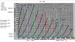
If your goal is 60mA anode current of 211, must to set grid voltage (setting it with Rset in my schematic) to about -50V (see datasheet).

As you can see, even 1100V, 65mA, -60V is correct operating point for 211.
Sample schematic, B+:960V, Ia:60mA:

If your goal is 60mA anode current of 211, must to set grid voltage (setting it with Rset in my schematic) to about -50V (see datasheet).

As you can see, even 1100V, 65mA, -60V is correct operating point for 211.
Sample schematic, B+:960V, Ia:60mA:

My bias supply is adjustable. I was able to measure the current 60mA(100 ohm installed). My fluke meter max DC 1000V
Try to measure 211 anode voltage, cathode current and grid voltage (bias) in working monoblock.
It may be near as in my sample schematic.
If the bias (grid)voltage isn't correct, the anode voltage is lower than expected and cathode current is high.
BTW Ongaku style PSU (if you use 5AR4 tubes and about 100R DCR/secondary part PT) without load (no working 211) produces 1058V.
If any capacitor damaging in this PSU, the doubler not working, so output (HT voltage) collapsing.
Will get help to check every component of the PS. Will the 510K resistor affect the voltage, should one of them become open circuit? Will 5AR4 affect voltage if one of them is faulty or shorted?
"Will the 510K resistor affect the voltage"
Practically not.
These resistors guaranteed equal voltages on series capacitors of doubler.
If one of the series capacitor shorting, the other possible also go bust and its equalizer resistor may burning. Then the output voltage collapsing.
If one of the rectifiers fails, the doubler still working, but voltage will lesser and ripple growing.
- Home
- Amplifiers
- Tubes / Valves
- Why voltage shot up