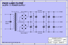
Somewhere else in this forum I read the suggestion to use two rectifier bridges instead of one, but i was wondering if there are other motivations apart from a (slightly) reduced output voltage and fewer thermal dissipation needed for each bridge..😕
I am building a Aleph 30 with a 500 VA 22V CT transformer (I know, 600> VA were better... but i had this one lying around), so I also need advice for lowering the rails voltage.
I was thinking about a coil between bridge and filtering caps, I guess about 1mH should be enough.. suggestions?
Thanks
andypairo
Hello Andypairo,
If you would use two diode bridges than it is better
idea to use transformer with two separate secondary
windings instead with the transformer that have
Center Tap.
Best regards,
Kristijan Kljucaric
http://web.vip.hr/pcb-design.vip
If you would use two diode bridges than it is better
idea to use transformer with two separate secondary
windings instead with the transformer that have
Center Tap.
Best regards,
Kristijan Kljucaric
http://web.vip.hr/pcb-design.vip
Attachments
Hi Andypairo,
I’m assuming you meant to say you have 44V CT. That would give you 22V to each bridge. A choke input PSU is going to give you too low a voltage for an Aleph 30. It calls for 25V rails and you’ll only have about 18V rails and less with higher loads.
I would go with Skaara on this one and run a PI filter PSU (CLC). If you use your 1mH (assuming low DC resistance), and add input and output caps like in Kristijan’s schematic, your rails will run from 23V to 26V (light load to high load) according to Duncans PSU Designer.
Hope this helps,
Rodd Yamas***a
Even though kristijan-k has come up with an excellent solution, the original question remains unanswered:
Why is 2 bridges better than one apart from the obvious (current capability, thermals etc.)
First of all, as kristijan-k has written, there is no gain unless you have two distinct secondary transformer windings. If you do, you can treat the two rails as separate entities and then connect their zero's
This allows you to take control of where large currents circulate, and not let that point be ground which is often by definition also "signal ground" and sensitive to noise induced from such currents.
If you have a center tap transformer there is no benefit from such an approach.
Herein lies the answer.
Petter
If you use one bridge with two secondaries and some
net DC current flows through the ground, there will be
a tendency toward saturation (and mechanical noise)
in the transformer if the two windings are not precisely
identical. Most of the time this is not a problem, but
when it is, two bridges prevents it.
net DC current flows through the ground, there will be
a tendency toward saturation (and mechanical noise)
in the transformer if the two windings are not precisely
identical. Most of the time this is not a problem, but
when it is, two bridges prevents it.
Thanks for the answers, I have 2 split secondaries and also a vibration problem (but only without inserting chokes,now I'm using a single bridge), you probably solved this problem...
The trafo is a toroid, so the secondary windings should be very closely similar but I'll give this method a try.
Another question: the service manual indicates 30000 uF per rail (and channel), kristijan-k's schematic more than twice (with the add of a choke).
Is the latter common to both channels?
I'll download also Duncan's PSU designer (Thanks roddyama) and will make some simulations by myself...
Andypairo
Petter said:Even though kristijan-k has come up with an excellent solution, the original question remains unanswered:
Why is 2 bridges better than one apart from the obvious (current capability, thermals etc.)
....
Herein lies the answer.
Petter
You got it! That's what I wanted to know...

By the way, my caps are a connected in a array-style since I only found 6800 uF ones.
Like this (I wish I had a digital camera..):
------------ -Rail
CCCCC - Caps
------------ Gnd
CCCCC Caps
------------ +Rail
Where shoul be placed Input (Bridge) and output (amp)connections?
1- In at the left, out at the right
2- Both in the same place (center?)
3- Somewhere else?
Hi
Andypairo

It doesnt matter if you gi from left to right of reversed!
You just have to connect them (electrically and physically) like i told you and like shown on kristjans schematic
You just have to connect them (electrically and physically) like i told you and like shown on kristjans schematic
Ok but what about star grounding or similar layout techniques?
Caps are connected by soldering on their pins a 2mmq wire, so I souldn't have series resistance problems, anyway I wanted to minimize it.
BTW placing smaller caps (say 100 uf or so on) close to the board(s) can help or it's overkill?
Hi
Andypairo
Caps are connected by soldering on their pins a 2mmq wire, so I souldn't have series resistance problems, anyway I wanted to minimize it.
BTW placing smaller caps (say 100 uf or so on) close to the board(s) can help or it's overkill?
Hi
Andypairo
Andyparo,
Please forgive me but I have misled you. The Aleph 30 will work fine with 23V – 26V rails as would the Aleph 3. I went to investigate the voltages and inadvertently looked at the Aleph 60. Don’t throw the chokes out yet because IMHO the PI filter PSU’s (even with just 1mH) are worth using, and in this case you might need them.
Sorry for the screw-up,
Rodd Yamas***a
Please forgive me but I have misled you.
 The Aleph 30 will work fine with 23V – 26V rails as would the Aleph 3. I went to investigate the voltages and inadvertently looked at the Aleph 60. Don’t throw the chokes out yet because IMHO the PI filter PSU’s (even with just 1mH) are worth using, and in this case you might need them.
Sorry for the screw-up,

Rodd Yamas***a
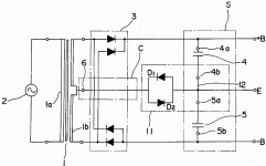
This patent from Onkyo may be of interest
<center><a href="http://164.195.100.11/netacgi/nph-Parser?Sect1=PTO1&Sect2=HITOFF&d=PALL&p=1&u=/netahtml/srchnum.htm&r=1&f=G&l=50&s1=4555751.WKU.&OS=PN/4555751&RS=PN/4555751">US Patent 4,555,751 Koga , et al. 26/11/85
Rectified and smoothed DC supplying circuitry</a></center>
Regards
James
<center><a href="http://164.195.100.11/netacgi/nph-Parser?Sect1=PTO1&Sect2=HITOFF&d=PALL&p=1&u=/netahtml/srchnum.htm&r=1&f=G&l=50&s1=4555751.WKU.&OS=PN/4555751&RS=PN/4555751">US Patent 4,555,751 Koga , et al. 26/11/85
Rectified and smoothed DC supplying circuitry</a></center>
Regards
James
Attachments
Great!
I have been looking for an answer to the double bridge question for sometime!
How about this one:
somewhere I have seen caps being added (take kristian drawing) from +PWR to
-PWR they are supposed to be useful in someway or another. Anyone care to shed some light on that?
I have been looking for an answer to the double bridge question for sometime!
How about this one:
somewhere I have seen caps being added (take kristian drawing) from +PWR to
-PWR they are supposed to be useful in someway or another. Anyone care to shed some light on that?
I would vote for no.2.------------ -Rail
CCCCC - Caps
------------ Gnd
CCCCC Caps
------------ +Rail
Where shoul be placed Input (Bridge) and output (amp)connections?
1- In at the left, out at the right
2- Both in the same place (center?)
3- Somewhere else?
If the group of caps is assumed as one unit,
the super symmetry about the center is considered
best, physically and electrically.
- Status
- Not open for further replies.
- Home
- Amplifiers
- Pass Labs
- Why two bridges are better than one?

