Hi
I have quite a good background in electronics,
yet the subject of a component requiring V+,Gnd,V- is new to me.
It seems that Class D amplifiers are of the Vcc,Gnd kind,
and Class AB amplifiers are of the V+,Gnd,V- kind..
Can anyone please explain it in a simple way?
Thank you
I have quite a good background in electronics,
yet the subject of a component requiring V+,Gnd,V- is new to me.
It seems that Class D amplifiers are of the Vcc,Gnd kind,
and Class AB amplifiers are of the V+,Gnd,V- kind..
Can anyone please explain it in a simple way?
Thank you
Solid state amplifiers using a single supply need some form of potential divider to give a central point for the output to lift and sink the output voltage to get the correct wave form shape. Then couple to your speaker through a DC blocking device, (capacitor) to usually the negative or ground connection.
Dual supply solid state amplifiers do not need a DC blocking capacitor for the loudspeaker as the centre or 0v point is ground. There is both +ve and -ve voltage available to lift and sink the output voltage. The speaker is directly coupled from the output line to the ground or 0v point.
Directly coupled speakers mean a lower frequency can be achieved as opposed to capacitor coupling that is governed by the capacitors low frequency response time for the loudspeaker.
All amplifiers can operate on a single DC supply. Every one of them. The reverse is not necessarily true. Split-supply amplifiers can be operated with differing voltage above and below ground reference. For example, you can have a supply of +40 and -20V instead of +/-30V. The only issue will be unequal swing in two polarities but the amplifier will operate fine.
Not that you would operate it like that, but basically the amplifier does not care which terminal is ground, just about the difference between the power supply's highest and lowest points. Many chip amplifiers have internal references that need to tie to circuit ground, and they usually expose a ground pin specifically for that purpose. One good way to tell a single supply chip is the absence of a separated GND pin, as they internally tie it down to one of the low side supply pins. These are mostly designed specifically for car or truck use, or some Class D amplifiers.
There are plenty of Class D chips that use split supplies. There are also plenty of Class AB chips that use single supplies. The use of an output capacitor is not an issue as long as the capacitor is properly sized. The bias voltage of 1/2 Vcc properly polarises the cap, making the sound quality not an issue either. There are many high-end Class A amplifiers using output capacitors and they work great after many years of service so that is not an issue either.
The use of an output capacitor helps provide some protection against DC faults, so that is at least a positive. Class D ampliifers operating off single supplies usually don't have an output capacitor (neither do most car amplifiers) because they are bridged and use two amplifiers per speaker. This means any potential at the output is effectively zero.
A lot of classD amps are single supply (VDD, GND) because they connect the speaker in BTL form. Which means 'bridge tied load' - so no output capacitor is required even though there's only a single rail.
Single rail amps I definitely prefer - the power supply is the most onerous part to get right in an amp IME so its best when there's only one instantiation needed. Sometimes the choice of number of rails is a function of heritage/application - for example chips designed for in-car use are practically always single rail whether classD or classAB.
Single rail amps I definitely prefer - the power supply is the most onerous part to get right in an amp IME so its best when there's only one instantiation needed. Sometimes the choice of number of rails is a function of heritage/application - for example chips designed for in-car use are practically always single rail whether classD or classAB.
Thank you for clarifying everything.
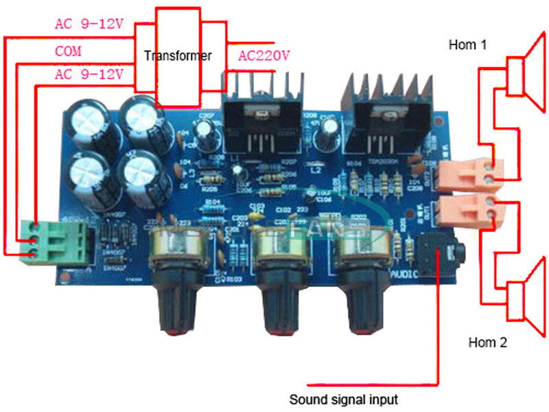
The left connector, expects twice an AC voltage..
(tho it does not say one is + and one is -.. what does it mean then?)
Please see this, for a Class AB TDA2030A amplifier..ALL amplifiers rely on DC supplies either split +/0/- or +/-.
If a design shows AC supplies then the DC conversion will be on-board.
The left connector, expects twice an AC voltage..
(tho it does not say one is + and one is -.. what does it mean then?)
Another thing regarding it,
usually, the transformer I saw in non audio circuits look like this:
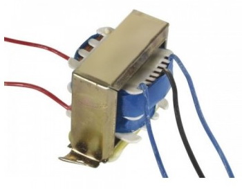
They have a metal core..
But in Audio circuits, especially ones that people upload here in DIYAudio,
the transformers look like this:
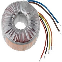
Toroidal shape, and no core..
When do we use the first one, and when the second one?
usually, the transformer I saw in non audio circuits look like this:
They have a metal core..
But in Audio circuits, especially ones that people upload here in DIYAudio,
the transformers look like this:
Toroidal shape, and no core..
When do we use the first one, and when the second one?
What does this mean?I have quite a good background in electronics,
")
Thank you for clarifying everything.
Please see this, for a Class AB TDA2030A amplifier..
The left connector, expects twice an AC voltage..
(tho it does not say one is + and one is -.. what does it mean then?)
The diodes and caps are clearly visible ion the bottom left
When and why you might use different types of transformers depends on space, location and application.
R Core and Toroidal transformers are generally more compact than their EI counterparts, especially when you start looking at very high power transformers.
However, Toroidal Transformers better couple any mains borne noise through to the DC output.
In a power amplifier a toroidal transformer would normally be the device of choice.
As you are not familiar with toroidals, also read VERY CAREFULLY any notes on SHORTED TURNS - They have to be mounted carefully.
- Status
- This old topic is closed. If you want to reopen this topic, contact a moderator using the "Report Post" button.
- Home
- Amplifiers
- Chip Amps
- Why Some Amplifier Chips Require only Vcc,Gnd, While Others Require V+,Gnd,V-?