Hello guys,I have a problem with my class d amplifier.
I have too much overshooting and I don't know how to stop it,I tried with snubers 10R+470pF and even 10R+1nF but nothing tried to reduce the oscilating frecvency to not more than 350kHz but still nothing 🙁
Can someone help with some advice? 😀 Thanks!
here is how PWM taken from switching node looks on osciloscope
https://www.youtube.com/watch?v=druc61j-F38
How is the scope probe grounded?
Gate drive waveforms?
Can you turn the sweep speed way up and trigger on one of the overshoot pulses, I want to see the ringdown.
Come on, give us a chance here.
Regards, Dan.
Gate drive waveforms?
Can you turn the sweep speed way up and trigger on one of the overshoot pulses, I want to see the ringdown.
Come on, give us a chance here.
Regards, Dan.
Hi Dan,tomorow i'll make the requested tests,now i'm trying to relax because tomorrow I go to work early in the morning. Thanks for understanding. John
That looks like a normal square wave to me. When you want a sharp risetime, there has to be some overshoot - that is just the nature of fast edge square waves. If this is the PWM leaving the amp and going into the LC filter, what gets out should be filtered way below audio frequencies and you don't see the overshoot. Just the analog representation of the PWM at the carrier frequency. Or are you showing us a square wave output of your amp at audio frequencies? If so, same thing. Show me a sharp risetime square wave that doesn't overshoot.
Hi xrk971,the square is taken at the switching node right betwen the mosfets where it goes to the filter L+C ,I have 10uH and 2uF cap (330nF X6 WIMA Polipropylene MK4). So this is OK.I forgot to mention that at the output I had some soft clipping 🙂
Show me a sharp risetime square wave that doesn't overshoot.
The shown time scale of 1us/grid is not suitable to judge whether it is a sharp rectangle or not in terms of class d amps.
For judging you need to zoom the time scale by factor 10...50.
dmills already highlighted the right questions.
Reasonable sloping times are somewhere in the range of 10ns...100ns
and should be controlled without overshoot or worst 10% under all load conditions.
It's mostly a question of layout and snubbering and correct probing.
Edit:
Bandwidth of the scope is 500MHz, well the probes are 450MHz.
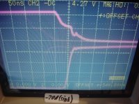
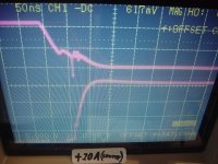
Attached a screen shot from the lite amp while it is sinking 20A load current.
Time scale is 50ns per horizontal grid.
Upper trace: Ugs of the low side switch, 5V per vertical grid
Lower trace: Half bridge output voltage, 20V per vertical grid
==> Halfbridge is rising within 30ns, without overshoot also at heavy load.
Attachments
Last edited:
Gate pulldown too fast can contribute a lot to that. If you whack the turn-off too hard the output inductor starts doing some impressive flyback. You can add a snubber or make the turn-off a little slower so the switch stays in the resistive region for more microseconds. Which way to go depends on where you want to put the dissipation and how close to detrimental cross conduction you are.
..true gate drive and also dead time adjustment will also have their influence.
Unnecessary fast drive is not always desirable as mentioned by Andrew.
Also to fast turn on can be headache, because this will cause extreme brute force removal of the Qrr and mad di/dt of the body diode snap back.
(Will turn visible in load situations 4 and 5 as described below).
In order to see where you are - typically six steady state measurements with will give a proper picture.
Here the method to get steady state operation modes which reflect all load situations.
Test set up:
Amp without input signal (input shorted).
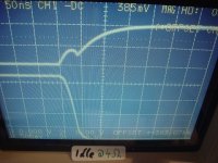
1) Idle/no load, event of turning off the low side MosFet
2) Idle/no load, event of turning on the low side MosFet
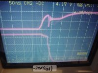
3) Sink load current. Resistor from pos rail to amp output, event of turning off the low side switch.
4) Sink load current. Resistor from pos rail to amp output, event of turning on the low side switch.
5) Source load current. Resistor from neg rail to amp output, event of turning off the low side switch.
6) Source load current. Resistor from neg rail to amp output, event of turning on the low side switch.
For measurements 3,4,5,6 start with reasonably small currents, because untamed and badly ringing half bridges will burn at higher currents.
Interesting current levels start when the load current is larger than the filter ripple current.
So measure - adjust - measure - adjust- measure - increase load - measure - ....
If you use an isolated floating power supply, then all this can be done even without the need of differential probes.
Do not try to simulate equivalent situations by applying DC to the amp input with load from amp output to GND. DC signal and load to GND would cause heavy bus pumping!
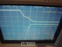
All attached screen shots were taken with the following settings:
Time scale is 50ns per horizontal grid.
Upper trace: Ugs of the low side switch, 5V per vertical grid
Lower trace: Half bridge output voltage, 20V per vertical grid
Unnecessary fast drive is not always desirable as mentioned by Andrew.
Also to fast turn on can be headache, because this will cause extreme brute force removal of the Qrr and mad di/dt of the body diode snap back.
(Will turn visible in load situations 4 and 5 as described below).
In order to see where you are - typically six steady state measurements with will give a proper picture.
Here the method to get steady state operation modes which reflect all load situations.
Test set up:
Amp without input signal (input shorted).
1) Idle/no load, event of turning off the low side MosFet
2) Idle/no load, event of turning on the low side MosFet
3) Sink load current. Resistor from pos rail to amp output, event of turning off the low side switch.
4) Sink load current. Resistor from pos rail to amp output, event of turning on the low side switch.
5) Source load current. Resistor from neg rail to amp output, event of turning off the low side switch.
6) Source load current. Resistor from neg rail to amp output, event of turning on the low side switch.
For measurements 3,4,5,6 start with reasonably small currents, because untamed and badly ringing half bridges will burn at higher currents.
Interesting current levels start when the load current is larger than the filter ripple current.
So measure - adjust - measure - adjust- measure - increase load - measure - ....
If you use an isolated floating power supply, then all this can be done even without the need of differential probes.
Do not try to simulate equivalent situations by applying DC to the amp input with load from amp output to GND. DC signal and load to GND would cause heavy bus pumping!
All attached screen shots were taken with the following settings:
Time scale is 50ns per horizontal grid.
Upper trace: Ugs of the low side switch, 5V per vertical grid
Lower trace: Half bridge output voltage, 20V per vertical grid
Attachments


- Status
- Not open for further replies.
- Home
- Amplifiers
- Class D
- Why so much overshooting