OMG, I think I figured it out...
So I was probing around the regulator with a multimeter and I touched the solder point for the heatsink - got 4v!
I heard somewhere that you should apply a small dab of thermal compound to each side of the mica when installing (makes sense to me from building PC's, and I had some lying around) - BUT, I think I shorted the regulator to the heatsink when the excess thermal compound squeezed out the sides when compressing the regulator to the heatsink.
I'm going to try to remove it with alcohol and q-tips (I cant get the heatsink off the board now).
I'll update you all if successful in removing the short.
Not Correct build is the problem
Yannie
First comes first. Heat-sink compound is not leading Electricity. It is not the Question of the compound spilling on to the heat-sink.
In between the Regulator cooling Tab and the Heat-sink you need a MICA washer then also you will need a Disc Washer which encloses the screw where passing the TAB of the Regulator. Meaning Tab of the Regulator and Heat-sink must be a totally NC= NO CONNECTION.
The heat sink itself need to be Grounded to Board Ground Secondary side.
When you get this correct, then the ripple will be gone.. the ripple is there because of OL.. I suppose..
For Measurements, there is no need to Measure INPUT or AC signal it will always show 50hz in full because it is the feeding Voltage of the Circuit..
Use a multi-meter if you want to know if Voltage is OK.
For Output to measure AC Segments or Ripple in the DC you need to switch the Oscilloscope to AC SIGNAL on that Channel even you are Measuring DC. Because you want to measure the AC SIGNAL in a DC Voltage so it can't be in DC Mode there is no way to measure AC Ripple Signal
Also you need to set the VOLTAGE UNIT to 200mv per unit on the Screen..then you will finally see the Actual Ripple of the Circuit you test. If you can not find Ripple with 200mv then adjust the Unit Voltage to 50millivolts or lower.
Do not be afraid, your scope can handle 300Volts RMS on the inputs so there is no need to switch the probe to x10. full screen on your Scope by setting to X1 is +- 20 volts when the input is set to 5Volts / Unit.
If you measure with your Probe X10 then the Scope input also must be set to X10 and measured Voltages must be multiplied by 10.
Make sure that you center horizontal and Vertical Trace prior to measure..
Hope this helps..
Send a Picture from the front of that RED Box you pull the power from.
All four resistance measurements you made earlier were on direct connections. A direct connection measures as maximum 1 Ohm with a multi-meter. In all four cases you measured more than 1 Ohm. I am convinced you have a problem with missing or poor platings such that a number of copper-tracks are not properly connected to copper-tracks on the opposite side, even if you have a component lead in that through-hole.
2 o'clock in France - good night for now.
2 o'clock in France - good night for now.
Last edited:
If you look at the board on the photo you referred to in posting #1, the solder has penetrated to the components side. But not on your board.
Thanks for chipping in, hpro, but we were using DC coupling on the 'scope because the 'ripple' was fully one-third or more of the average DC voltage -- not the more typical millivolts.
I think FauxFrench is onto something -- even a commercially-produced board can have thru-plating issues.
Then there is still the issue of the LD1084 having possibly been exposed to 34 to 37V in one of the 'rolling up the voltage to 24V(ac-rms)' tests.
Glad you're fixing the '4V DC on the heatsink' issue.
Regards
Since you fellers will probably be back at it tomorrow before me, thought it worth adding that several other points of hpro's are sound, too.
Cheers
Cheers
I have seen that.. and it caused me to think what went wrongThanks for chipping in, hpro, but we were using DC coupling on the 'scope because the 'ripple' was fully one-third or more of the average DC voltage -- not the more typical millivolts.
Regards
He has a diodes bridged with 2 10000 uf Capacitors. ripple should not be more then 200 Milli-volts. 0.2 before the Regulator, so something must be really wrong.
Now, and that's why I suggested about the AC is, get that measurement again, Straight to the OSC nothing in between with a good ground connection.
So, the short on the housing of that Regulator explains much more..
Hi all,
So I'm NEW to building electronics - so thanks in advance for your patience with me haha.
I bought this with the 2.5" heatsink option and 12vdc output.
I rolled up the voltage from 0-18vac and cannot get a clean 12vdc output voltage on it. What am I missing here?
Here's a photo off the scope:
An externally hosted image should be here but it was not working when we last tested it.
Yannie,
We need to go back to Square 1. Restart that from beginning.
I'm suspicious why someone uses a Adjustable Voltage Regualtor for and output of 12Volts, but there isn;t a pot on the PCB to adjust.!!???
this makes me think that either the person who did designed this Regulator Board used the wrong Regulator or for whatever reason I don't know.
OK square one means:
1. Desolder and remove the Regulator complete
2. Solder a Wire to the + of the big Capacitor that you can clipon a DVM
3. Apply AC Power Cables to the PCB
3. Switch on Power. Depending on the AC Voltage you will get a DC Voltage at the Cable you soldered to the Capacitor. If you apply 24 Volts the reading should be 24 X 1.414= 33.936 Volts DC may it's a bit lower but ist should not be higher.. or more than 35Volts DC
4. Hook up the OSC to the Capacitor, switch to AC inpput and Measure RIPPLE. Without LOAD there should not be more than MAX 250millivolts Ripple.
5. Shut off, Discharge the CAPACITORS with a 500 OHM Resistor.
Just palce the Resistor across the +- of the Cap. Disconnect the Cables and remove that cable you earlier soldered to the Capacitor.
6. Solder the Regulator into the board
Make sure that the CENTER TAB is ISOLATED against the HEATSINK
7. Make sure that the HEATSINK is grounded to the PCB MINUS POL.
8. Apply the AC CABLES again and Switch on.
9. Check the OUTPUT at REGULATOR OUT.. It has to be the voltage of the REGULATORS design. Supposedly 12 Volts.
I can make an illustration for you when I'm home tonight.. if you like..
If you go be this Step by Step it will work just fine.
Check out this
Yannie
just post that you understand the last post of me.
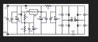
This is a copy of the Diode Section of your Regulator PCB.
This is where you need to measure Voltage with removed Regulator.
Testpoint 1.
If you feed AC Voltages with 12 Volts per connection point then you will have a DC OUTPUT VOLTAGE of = 12*1.414= 16.968 or almost 17 Volts at the output to Regulator or on Pin 3 of the Regulator. Pin 3 is the Right side Pin when you look at the regulator from to front side where you can read the NAME of it.
Testpoint 1 is also the Point where you can connect the OSC Probe to measure Ripple from Diode Section.. Continue if at thisk Point everything is OK. and RIPPLE is less than 300Millivolts.
Again, Take caution that the Center TAB of the Regulator is Isolated from Ground and Heatsink. Use DVM switched to OHM and measure for Short circuit.
As you use AC Voltages on both Connection Points make sure that the GROUND WIRE of your Transformer is connected to GND of your PCB which has been named CT in the circuit. The output Voltage of your Transformer is meant per Wire measured agianst CENTER TAB of the Transformer 15Volts then Calculation is 15 * 1.414 = 21.21Volts DC..This always is for both wires as you use a Full Bridge Configuration of the DIODES.
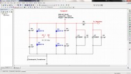
Look at my drawings, this is the same as on your PCB, don't give the Names of the components any intererest because these are only Placeholders so that I can draw it in the program.. Programm is Multisim 14.
Hope this helps.
Yannie
just post that you understand the last post of me.
This is a copy of the Diode Section of your Regulator PCB.
This is where you need to measure Voltage with removed Regulator.
Testpoint 1.
If you feed AC Voltages with 12 Volts per connection point then you will have a DC OUTPUT VOLTAGE of = 12*1.414= 16.968 or almost 17 Volts at the output to Regulator or on Pin 3 of the Regulator. Pin 3 is the Right side Pin when you look at the regulator from to front side where you can read the NAME of it.
Testpoint 1 is also the Point where you can connect the OSC Probe to measure Ripple from Diode Section.. Continue if at thisk Point everything is OK. and RIPPLE is less than 300Millivolts.
Again, Take caution that the Center TAB of the Regulator is Isolated from Ground and Heatsink. Use DVM switched to OHM and measure for Short circuit.
As you use AC Voltages on both Connection Points make sure that the GROUND WIRE of your Transformer is connected to GND of your PCB which has been named CT in the circuit. The output Voltage of your Transformer is meant per Wire measured agianst CENTER TAB of the Transformer 15Volts then Calculation is 15 * 1.414 = 21.21Volts DC..This always is for both wires as you use a Full Bridge Configuration of the DIODES.
Look at my drawings, this is the same as on your PCB, don't give the Names of the components any intererest because these are only Placeholders so that I can draw it in the program.. Programm is Multisim 14.
Hope this helps.
Attachments
Last edited:
If I understood correctly from earlier, this transformer is dual secondary that Yannie plans separate uses for -- no center tap on either winding. Maybe there is some confusion around that ..
For now, I'm betting on the 4V-on-the-heatsink issue being the culprit.
Cheers
For now, I'm betting on the 4V-on-the-heatsink issue being the culprit.
Cheers
Take look at the Pictures
n
I wasn't able to see dual Secondary.. All I saw was a single Secondary. So if he connects it to AC then GROUND IS MISSING.
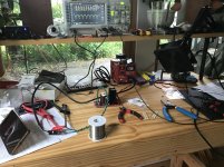
I place his Picture here one more time.
Check out the green Leads for AC
But nowhere is a ground lead to find, which goes back to the transformer. This is essential to have no noise. I know it can be run like that, but for me this is a first grade error. Regulator is running without GND
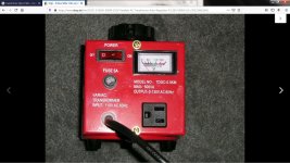
The Transformer is the red box in the back. I suppose the transformer step down step up Transformer. DO NO USE IN ELECTRONICS. Here I found that Picture of his Transformer. With this transformer it is a no go.
n
I took a look at the Pictures where he hooked up the REGULATOR circuit..If I understood correctly from earlier, this transformer is dual secondary that Yannie plans separate uses for -- no center tap on either winding. Maybe there is some confusion around that ..
For now, I'm betting on the 4V-on-the-heatsink issue being the culprit.
Cheers
I wasn't able to see dual Secondary.. All I saw was a single Secondary. So if he connects it to AC then GROUND IS MISSING.
I place his Picture here one more time.
Check out the green Leads for AC
But nowhere is a ground lead to find, which goes back to the transformer. This is essential to have no noise. I know it can be run like that, but for me this is a first grade error. Regulator is running without GND
The Transformer is the red box in the back. I suppose the transformer step down step up Transformer. DO NO USE IN ELECTRONICS. Here I found that Picture of his Transformer. With this transformer it is a no go.
Attachments
Last edited:
Sorry, my bad. I looked up the 120VA toroid he spec'd earlier and assumed it was installed. Definitely shoulda looked closer at that pic! 😱
Yannie, good sir: You simply must discontinue testing like this! When your 120VA toroidal transformer arrives -- or you secure an isolation transformer to borrow -- you can resume this work.
If the LD1084 is the only fatality from this it is VERY fortunate.
Pretty sure the ground hpro speaks of is Earth, which properly comes from the wall outlet, not the transformer. To get full wave juice out of this requires No Connection to a transformer winding center tap, if there is one.
I guess Yannie's variac isn't plugged into a GFI-protected outlet !! 😉
Thanks hpro!
Cheers
Last edited:
Hi all,
Thank you all so much for the comments - I saw the emails coming in throughout the day but had to work all day today. I'll be back on this project tomorrow and will update the thread as I move forward with your suggestions!
Thanks again!
Thank you all so much for the comments - I saw the emails coming in throughout the day but had to work all day today. I'll be back on this project tomorrow and will update the thread as I move forward with your suggestions!
Thanks again!
About Cirquit and Center Tab
I'm going by the cirquit and the way it was designed. In the circuit there is definately a CT = Center Tab drawn. Together with Ground of the Output of that Regulator PCB.
I know and I Agree with you that FUll WAVE Rectifying doesn't need a CT.
But it is there, either on mistake or on purpose. this is what I'm talking about the whole time.
And if you look at the Picture well then you can see on the left side where the AC voltage is fed to the PCB there is also a white/Grey little Box connected too and this one is connected to the Scope.. I don't need to tell you what this is.. To keep AC LINE VOLTAGE out of the OSC input..
What Yannie does here, is not only wrong to start with but also dangerous, becaue we don't know how the connection are in that Variac Box. See the plug then you know that this is not MADE for LOW VOLTAGE USE, meaning someone eventually can get an electric shock if this someone touches the bare output wires..
Check out the added Picture of the circuit
My two cents..
In Swiss and Europe these kind of Transformes are usually forbidden to sale.
Regards Chris
Rick,Sorry, my bad. I looked up the 120VA toroid he spec'd earlier and assumed it was installed. Definitely shoulda looked closer at that pic! 😱
Pretty sure the ground hpro speaks of is Earth, which properly comes from the wall outlet, not the transformer. To get full wave juice out of this requires No Connection to a transformer winding center tap, if there is one.
Thanks hpro!
Cheers
I'm going by the cirquit and the way it was designed. In the circuit there is definately a CT = Center Tab drawn. Together with Ground of the Output of that Regulator PCB.
I know and I Agree with you that FUll WAVE Rectifying doesn't need a CT.
But it is there, either on mistake or on purpose. this is what I'm talking about the whole time.
And if you look at the Picture well then you can see on the left side where the AC voltage is fed to the PCB there is also a white/Grey little Box connected too and this one is connected to the Scope.. I don't need to tell you what this is.. To keep AC LINE VOLTAGE out of the OSC input..
What Yannie does here, is not only wrong to start with but also dangerous, becaue we don't know how the connection are in that Variac Box. See the plug then you know that this is not MADE for LOW VOLTAGE USE, meaning someone eventually can get an electric shock if this someone touches the bare output wires..
Check out the added Picture of the circuit
My two cents..
In Swiss and Europe these kind of Transformes are usually forbidden to sale.
Regards Chris
Attachments
+1 hpro -- methinks we're swinging at the same nail .. but it did take me a while to get there. And thanks for being gentle!
And .. assume we agree that using the CT (connection point - for such a transformer - in your schematic thumbnail) requires that D1 and D3 be removed/not fitted.
Plus, you guys have 220/240V in your neighborhood, eh?! Quite a bit more zing to promptly correct any mistakes!
Regards
And .. assume we agree that using the CT (connection point - for such a transformer - in your schematic thumbnail) requires that D1 and D3 be removed/not fitted.
Plus, you guys have 220/240V in your neighborhood, eh?! Quite a bit more zing to promptly correct any mistakes!
Regards
This is not my schematics, this is the original from the Vendor of this BOARD.. Find it on Yannies first post.. that's the reason for my followups..+1 hpro -- methinks we're swinging at the same nail .. but it did take me a while to get there. And thanks for being gentle!
And .. assume we agree that using the CT (connection point - for such a transformer - in your schematic thumbnail) requires that D1 and D3 be removed/not fitted.
Plus, you guys have 220/240V in your neighborhood, eh?! Quite a bit more zing to promptly correct any mistakes!
Regards
Your welcome
Enjoy Weekend..
Chris
- It isn't a transformer, as I see. It is auto-transformer (variac). The difference is in absence of galvanic isolation. (Among other things it may cause a high level of ripple).n
The Transformer is the red box in the back. I suppose the transformer step down step up Transformer. DO NO USE IN ELECTRONICS. Here I found that Picture of his Transformer. With this transformer it is a no go.
Is there an isolating transformer somewhere before that variac?
Last edited:
- It isn't a transformer, as I see. It is auto-transformer (variac). The difference is in absence of galvanic isolation. (Among other things it may cause a high level of ripple).
Is there an isolating transformer somewhere before that variac?
Besides that it's dangerous as well..
We call this step up step down Transformer - Means exactly Variac.
Hey guys,
Thanks for checking in - I’ve been slammed at work and have been off my bench for a bit now... hoping I’ll get some free time this weekend to get back on it and go through all the messages you guys have left. I have some work to do on the board, and will update everyone with the results of your recommendations asap.
Thanks again, sorry about the delay.
- Home
- Amplifiers
- Power Supplies
- Why so much DC ripple?