Hi everyone.
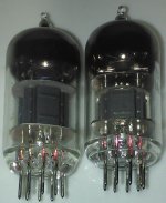
Does anyone know why the plates of these 12AX7 are so much different?
I have a third one around, which is closer to the one on the right (image attached).
According to analytical studies, the amplification factor of a triode increases as the distance between grid and plate increases. But the depth difference of the plates of these two models is just huge. I didn't find any specific information about this. Any comment is very much apprecited.
This is not exclusive of 12AX7s. Same thing happends with a pair of 12AU7.
Attachments

Plate size depend of plate disipation, but as this tubes usually work well under their maximum ratings, perhaps decreasing plate size saves cost.
Compactron 6U11 has two units in a single 12 pin tube: a 12AX7 plus one unit from 12AU7, but wastes only 600mA of heater, so one unit is "free" saving 300mA.
Compactron 6U11 has two units in a single 12 pin tube: a 12AX7 plus one unit from 12AU7, but wastes only 600mA of heater, so one unit is "free" saving 300mA.
I bet geometry is similar between the two. Looks like they rotated the cathode/grid 90 degrees in the second one. I'd bet the other dimension is about the same as what the picture on the left is.
I bet geometry is similar between the two. Looks like they rotated the cathode/grid 90 degrees in the second one. I'd bet the other dimension is about the same as what the picture on the left is.
And the grid support rods seem to be placed in the same orientation.
Attachments
And the grid support rods seem to be placed in the same orientation.
Are they? I couldn't tell from the pictures. I do have many later manufacture 12ax7s that are rotated 90 degrees and don't have the welded plate seams in line with the grid support rods, so I thought this might be the same.
Little known fact…
Most of the mu of a valve depends on the inter-grid spiral spacing and the distance from the shell-of-the-cathode to each concentric grid. The anode can be near or 3× as far (on the scale of cathode-to-grid-(to-grid)*-to-anode measure), and won't change mu much at all.
However, anode-being-farther-away increases the maximum tension (i.e. anode-to-cathode voltage) that is allowable for a given design.
You can see this especially with high-tension TV flyback rectifier tubes.
The cathode is an itty-bitty thing, but the anode is large, and even has physically rounded edges, to suppress arcing … at 35+ kilovolts of blocking tension. If made smaller in radius, arcing would happen. The larger anode can also serves — probably obvious — to dissipate more waste-heat power.
Always good with flyback rectifiers.
So… so long as the mu and transconductance curves of the given 12AX7 (or any other family) design are adhere'd to, then whether the plates are larger, or smaller, doesn't much matter.
The exception would be if you're driving the AX7's at high tension, where the larger, further anodes would have a better chance of tolerating the tension without BLAM degeneration.
Just Saying,
GoatGuy ✓
It's an excellent question, and one that interests lots of people, but I don't think you'll get any useful answers on an Internet website, even this one. Valves were built from proprietary experience and largely ad hoc, and all before any ideas of computer modeling.
The idealized 3/2 power function comes from infinite parallel planes with equal charge everywhere, among other gross simplifications. If any big semiconductor manufacturer were to spend the Big Bux to adapt their proprietary design software to vacuum valves, amazing new valves could be designed. (not *built* - that's another Big Bux to spend just to duplicate ancient tech) But that can't possibly be paid for, so can't happen.
Our current knowledge of valve design isn't very different from archeology. The same will soon enough be true for our current semiconductor processes. You don't believe me now, but half a century will tell the tale.
All good fortune,
Chris
There are a few reference books about valve design, such as the well known RCA electron tube design compilation of articles: Vacuum Tube Manual: RCA 1962 Electron Tube Design : Free Download, Borrow, and Streaming : Internet Archive ; the paper at page 669, as example, gives many details about the internal structure of audio output power tubes (materials, spacings, shapes and so on). This is a lot more than archeology grade knowledge.
Yes. That's an interesting book. Slight differences in the plate can be easily compensated with changes in the grid and cathode.
Are they both marked ECC83 or 12AX7?
Comparing the pictures in post#1, the righthand tube seem to have a shield between the two triodes.
The left-hand tube is similar to some ECC83 i have compared to.
The right hand tube is not unlike (the only) 7025 tube in my stash.
Comparing the pictures in post#1, the righthand tube seem to have a shield between the two triodes.
The left-hand tube is similar to some ECC83 i have compared to.
The right hand tube is not unlike (the only) 7025 tube in my stash.
12AX7EH and 12AX7AW
Most 12AX7 I have are much more like the one on the right.
Anyway, all of them have same parameters (according to their manufacturer's datasheet).
Most 12AX7 I have are much more like the one on the right.
Anyway, all of them have same parameters (according to their manufacturer's datasheet).
Does anyone know why the plates of these 12AX7 are so much different?
That would be because of their design as specs were already layed down for the specific type. Different factories arrived at different solutions, inter electrode capacitance would be the greatest obstacle. Telefunken novals were sold with a promissed life time, followed by Philips Special Quality and Mullard 10K. Same specs as ECC83 / 12AX7 but intended for high demanding circuits for scientific applications etc.
Did anybody notice there are lots of long plate 12AX7, and lots of short plate 12AX7?
I am pretty sure there are good sounding long plate models, and good sounding short plate models.
Put them in your amplifier.
Listen.
If they are used with lots of negative feedback around them, do not expect to hear much of a difference.
If you hear lots of difference, there is likely one of two causes:
No negative feedback, and one intrinsically has more distortion.
One is really bad.
Last edited:


There are even frame grid ECC83 variants with even shorter plates, the venerable TELEFUNKEN ECC803S and the J/J ECC83S. All having the same 12AX7 electrical data.
Best regards!
Best regards!
Don't forget TESLA framegrid and JJ E83CC framegridThere are even frame grid ECC83 variants with even shorter plates, the venerable TELEFUNKEN ECC803S and the J/J ECC83S. All having the same 12AX7 electrical data.
Best regards!
All of the above has very short plates.
There are even frame grid ECC83 variants with even shorter plates, the venerable TELEFUNKEN ECC803S and the J/J ECC83S. All having the same 12AX7 electrical data.
Best regards!
True. But I think that it is the distance between anode and grid what, among other factors, defines mu. It seems logical to think that long or short plates shouldn't compensate for narrow plates. And, as we all know, all 12AX7 have a quite high mu.
As always, there are many ways to skin a cat.
Btw, I'd be quite interested in how they calculated the structural topography to yield a certain goal.
Best regards!
Btw, I'd be quite interested in how they calculated the structural topography to yield a certain goal.
Best regards!
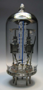
How about this little beauty, 21st century ECC83 with a direct connection to Mullard ...
E813CC
Saw this on this blog about the old Mullard site in Blackburn, which was a great read ...
Tour of the old Mullard site in multiple parts
E813CC
Saw this on this blog about the old Mullard site in Blackburn, which was a great read ...
Tour of the old Mullard site in multiple parts
Attachments
- Home
- Amplifiers
- Tubes / Valves
- Why so different plate size for same model?