I tried this idea to drive the balanced output of my Roland E660 in a gainclone. Used chips are OPA549. No bad smell, no DC on the output but also no sound 😕 They are powered with 2 12v batteries wich gives a -12 and +12 rail. Also there's a 0,1 µF cap over the 2 rails.
Even when i connect just one on a unbalanced output still nothing.
The only thing i hear is a slight *pop* in the speakers when I power the 549's.
An externally hosted image should be here but it was not working when we last tested it.
Even when i connect just one on a unbalanced output still nothing.
The only thing i hear is a slight *pop* in the speakers when I power the 549's.
i asume you mean the OPA549? what have you connected the current limiting and Vref pins to? there will be no output unless the are both set. the easiest way to do this is to connect them both to ground. this will set the current limit to maximum (10A).
have fun. 😀
have fun. 😀
both are connected to the ground, wich in this case is the plus and minus from each batterie. -12 gnd +12
Is the ground of output from the Roland connected to anything? Quite often balanced outputs are created without a transformer, and since your input is transformerless, you really need to connect the grounds together.
Rune
Rune
yup, those are connected to the ground as well.
mmm, i was fiddeling a bit. Now i got his very hard sounding clipping music true the speakers. Well not music, more static/hum on the beat of the song.
mmm, i was fiddeling a bit. Now i got his very hard sounding clipping music true the speakers. Well not music, more static/hum on the beat of the song.
SpaBlauw said:both are connected to the ground, wich in this case is the plus and minus from each batterie. -12 gnd +12
yes.
sorry to hear about the hum. i cant really help more, as i dont know anything about balanced inputs/outputs.
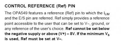
I just red the datasheet over again, in wich stated that ref. pin must be als low as the negative voltage if V- is used. So in my case -12. Sadly enough I don't have anymore samples avaible so this project has to wait.
@carlosfm, actually this is a bridgeclone. But you can call it a balanced amplifier since you use the - in / + in to drive it.
@carlosfm, actually this is a bridgeclone. But you can call it a balanced amplifier since you use the - in / + in to drive it.
What have you done with the E/S pin? (It shouldn't be connected to anything when REF and ILIM is at GND)
As long as you have a psu voltage above +/- 4V, you can connect REF and ILIM to GND. 😉
As long as you have a psu voltage above +/- 4V, you can connect REF and ILIM to GND. 😉
Right. As I look closer on your schematic on top of the page, it seems that you have reversed the psu lines? V+ should be connected to 10,11 and V- to 5,7.🙁
SpaBlauw said:I just red the datasheet over again, in wich stated that ref. pin must be als low as the negative voltage if V- is used. So in my case -12. Sadly enough I don't have anymore samples avaible so this project has to wait.
@carlosfm, actually this is a bridgeclone. But you can call it a balanced amplifier since you use the - in / + in to drive it.
oops, sorry. i forgot that they go to -v.

Matttcattt said:
oops, sorry. i forgot that they go to -v.
what do you mean by that?
Attachments
Mad_K said:Right. As I look closer on your schematic on top of the page, it seems that you have reversed the psu lines? V+ should be connected to 10,11 and V- to 5,7.🙁
Yup you are right, but i solderd it the right way. So +V is on pin 10/11
SpaBlauw said:
Yup you are right, but i solderd it the right way. So +V is on pin 10/11
What kind of DC offset do you get at each amp/output to GND?
Mad_K said:
what do you mean by that?
i meant that i forgot that in my amp, i connected the ref and Ilim pins to the -v rail. (before i said that i connected them to ground).
- Status
- Not open for further replies.
- Home
- Amplifiers
- Chip Amps
- why o why doesn't this work ? Balanced 549