There are some. Nelson Pass has got some for example.
Schematic? 98%+ of the amps I see posted here are single ended output.
Nelson Pass - >Son of Zen<
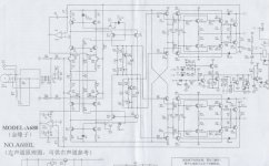
Accuphase A-680 is the other good example - well, much more complicated - see attached.
Cheers,
Valery
Accuphase A-680 is the other good example - well, much more complicated - see attached.
Cheers,
Valery
Attachments
Do you mean Balanced impedance input and Balanced impedance output?
or are you adopting the "opamp" manufacturers' definition of fully differential?
or are you adopting the "opamp" manufacturers' definition of fully differential?
Do you mean Balanced impedance input and Balanced impedance output?
or are you adopting the "opamp" manufacturers' definition of fully differential?
The definition I am using is a fully differential path from input to output. Meaning no single ended signal path the entire circuit such as the standard current mirror load at the input stage, but instead a CMFB current source load. Also a fully differential driver and output stage.
That means, if I read you correctly, you are not adopting Balanced impedance principles.
What performance improvement will come from adopting fully differential?
What performance improvement will come from adopting fully differential?
That means, if I read you correctly, you are not adopting Balanced impedance principles.
What performance improvement will come from adopting fully differential?
Actually it was more of a theoretical question, I'm not claiming fully differential audio amplifiers offer any meaningful advantage over single ended. I'm sure there are a lot of practical reasons (transistor count, more bias adjustments, complexity, etc) why they aren't common, but from a DIY standpoint I was just surprised I almost never see fully differential circuits attempted on a DIY forum even just for fun.
I was just playing with some fully differential spice circuits the other day and wondered.
differential signaling with balanced transmitter and receivers are extremely common in pro audio
fully differential circuits can need the help of common mode servos - which you might say spoil the symmetry
fully differential circuits can need the help of common mode servos - which you might say spoil the symmetry
If you really mean fully differential, so at no point is the signal just a single voltage (with respect to some ground reference, of course) then one problem is that you essentially have two signal paths which usually means non-minimum phase which can lead to stability issues. You have twice as many components to do the same job, no real advantages, and some disadvantages.
If something is not common then there is usually a good reason for this.
If something is not common then there is usually a good reason for this.
Pro audio usually uses balanced lines outside equipment (and sometimes for specific applications inside), but generally almost the first thing you do at an input is unbalance the line.
Regards, Dan.
Regards, Dan.
This DIY A class amp design is fully differential from input to output :
http://www.diyaudio.com/forums/solid-state/270239-i-call-infinitron.html
http://www.diyaudio.com/forums/solid-state/270239-i-call-infinitron.html
Yes, there are good reasons why lines are balanced. These reasons do not apply to circuits, so most circuits are unbalanced.
Banat, thanks for that.
I note the "crossover" NFB.
I also note what looks like single ended amplifier stages in the two halves of the differential.
which Fusion wants to reject
I note the "crossover" NFB.
I also note what looks like single ended amplifier stages in the two halves of the differential.
which Fusion wants to reject
Schematic? 98%+ of the amps I see posted here are single ended output.
Actually it was more of a theoretical question, I'm not claiming fully differential audio amplifiers offer any meaningful advantage over single ended. I'm sure there are a lot of practical reasons (transistor count, more bias adjustments, complexity, etc) why they aren't common, but from a DIY standpoint I was just surprised I almost never see fully differential circuits attempted on a DIY forum even just for fun.
I was just playing with some fully differential spice circuits the other day and wondered.
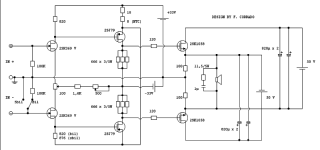
Hello, actually they were posted in other threads some of my circuits that fall into this category.
And looking to the attached pictures, it appears that not count twice the number of components compared to other amplifiers of the same power size, pheraps the contrary.
Given the overwhelming use of unbalanced connections, they have the RCA inputs (single ended), but schematics can easily be changed to acceipt XLR.
However, if you have balanced signals, this change I recommend only for the smaller of the two.
Whereas, because also if your system provides balanced signals they will be probably obtained with op-amps, I would not recommend this change to the biggest amp.
In fact, it incorporates a phase splitter of the highest quality for the generation of the two differential signals necessary to the power stage.
Also, in the more powerful scheme, with minor adjustments in the driver, you can also easily replace those greedy devices (SIT) with the most common Mosfet, Bjt, Sic JFET, etc.
Attachments
I had some trouble following the schematics (the first one seems to be drawn to look more symmetrical then it really is), but you may wish to consider most carefully what happens with a couple of volts of common mode up the input, because I don't think it does the output stage DC conditions any favors.
Ensuring near zero common mode gain is one of the many reasons to unbalance early in the design.
Regards, Dan.
Ensuring near zero common mode gain is one of the many reasons to unbalance early in the design.
Regards, Dan.
The definition I am using is a fully differential path from input to output. Meaning no single ended signal path the entire circuit such as the standard current mirror load at the input stage, but instead a CMFB current source load. Also a fully differential driver and output stage.
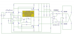
Something like my bridge amp? I recall that prototype worked quite well.🙂 No inferior op-amp phase splitting used here, high quality phase splitter circuit included....perfect phase alignment even at 1MHz.😎
The completed amp includes the phase splitting circuit, voltage regulator circuits for the VAS and IPS, the VAS circuit, and DC servo circuit all as daughter boards. The EC mosfet output stage circuits are on the main board. The TO-220 output devices are on the bottom of heatsink bracket and the TO-126 EC transistors are on the top side.
Last edited:
I had some trouble following the schematics (the first one seems to be drawn to look more symmetrical then it really is), but you may wish to consider most carefully what happens with a couple of volts of common mode up the input, because I don't think it does the output stage DC conditions any favors.
Ensuring near zero common mode gain is one of the many reasons to unbalance early in the design.
Regards, Dan.
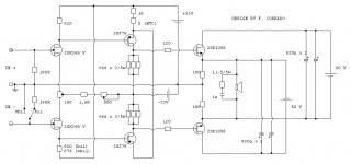
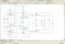
Thanks to you Dan, I have realized that there is a mistake in how I designed the circuit.
I attach here the correct one.
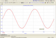
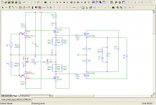
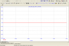
BTW, in the following post I am attaching instead the simulations of the circuit with the relatively transient analysis when there are present differential signals at the inputs, and in the subsequent simulation when the same are presented as common mode signals. In the latter case the cancellation is almost perfect.
P.S:Note because I not have a model of 2SK369V, in simulator i have used 2SK170V (it is much similar).
Attachments
- Status
- Not open for further replies.
- Home
- Amplifiers
- Solid State
- Why no fully differential circuits?