I am frustrated with my speakers that i put a lot of time and learning into building and I still have a nagging problem of no bass with my system.
My design goals were to create a system with high SPL and extended frequency range. My amp is only about 50 WPC, so efficient speakers are pretty much a must. I use these for playing music mostly.
The speaker is a 3-way with a 15" JBL 2235H woofer, an Audax PR170M0 for the mid, and a Morel MDT-37 tweeter.
The mid and tweeter are in their own sub-cabinet. The 2235H is in a 6 cubic foot ported enclosure with two 3.95" diameter flared vents 6" long (tuned to 32 Hz).
I should see a flat response down to at least 35 Hz (according to LEAP and Bass Box Pro), but it dies at about 55 Hz.
Madisound designed the 3-way crossover using LEAP. It sounds great, except the lack of bass.
Anyone have any ideas?
Using my program I get tuning of 35hz with that port and f3 of 40hz.
Nevertheless, if your amp is delivering 30 watts to the JBLs you should be getting output of 111 db at 50 hz and 108 db at 40. Not exactly a textbook sub but you should be hearing plenty of bass.
Do you have any serious leaks in the box? If not, I'd look at the amp.
Have you tried blocking one of the ports?
It seems to me (not that knowledgeable) there is too much port area relative to the cabinet and driver dimensions.
Even if there is no theory to support reducing the port area, it will only take a minute or so to find out the effect.
It seems to me (not that knowledgeable) there is too much port area relative to the cabinet and driver dimensions.
Even if there is no theory to support reducing the port area, it will only take a minute or so to find out the effect.
Blocking one port would make the problem even worse, as the tuning frequency goes down by 2^0.5
By the way - there is no such thing as "too much" port area. In my opinion the port area should be larger than the driver area, as it can output much more sound at the tuning frequency than the driver alone can do.
By the way - there is no such thing as "too much" port area. In my opinion the port area should be larger than the driver area, as it can output much more sound at the tuning frequency than the driver alone can do.
Last edited:
Blocking one port would make the problem even worse, as the tuning frequency goes down by 2^0.5
By the way - there is no such thing as "too much" port area. In my opinion the port area should be larger than the driver area, as it can output much more sound at the tuning frequency than the driver alone can do.
Stig - I don't think I understand. Isn't the tuning freq determined by the port? So there's no point in calculating port size to tune the box? Should we just leave the back off the box and call it a port?
Does that make it a U Frame?
The tuning frequency is detemined by three factors: enclosure volume, port area and port length. If you change one of the three, the tuning frequency is also changed of course.
If you want to make a bigger port area you must also make the port longer.
Reducing the port area alone (by blocking one of two ports) will lower the tuning frequency.
My point with the port area is that the smaller the port, the more compression you'll get. Say a 2" port with a 15" driver will not work as a port at all because the port airspeed will get too high, and compression is the result. To avoid too much compression, the ports should really be as large as the driver, but that will usually result in very long ports, which create new problems.
Understood - I misinterpreted your post to mean you could increase port area without considering box volume, tuning, length. All too often I get excited about some modeling results and see that the port length specified is twice as long as the longest box dimension. Start over.
The tuning frequency is detemined by three factors: enclosure volume, port area and port length. If you change one of the three, the tuning frequency is also changed of course.
If you want to make a bigger port area you must also make the port longer.
Reducing the port area alone (by blocking one of two ports) will lower the tuning frequency.
My point with the port area is that the smaller the port, the more compression you'll get. Say a 2" port with a 15" driver will not work as a port at all because the port airspeed will get too high, and compression is the result. To avoid too much compression, the ports should really be as large as the driver, but that will usually result in very long ports, which create new problems.
Realistically, I don't think the port area needs to be that large. If memory serves, keeping vent speed under 5% of the speed of sound (17 m/s) is a good rule of thumb. Below that speed it should not be audible.
In this design the maximum vent speed is about 14 m/s at 150 Watts. My amp produces a maximum of 60 Watts and at that amplitude the maximum vent speed drops to about 10 m/s. So, audible chuffing should not be an issue in this design.
Flaring a vent further improves performance as far as compression is concerned. Only one end is flared in my design due to internal space interference, but I should be able to correct that with a little work sometime in the future.
Right - you dont need large ports to avoid wind noises, but you will get severe compression losses long before you hear any wind noise. Flaring the port ends will not help the compression problem I'm afraid.
Dickason has done some interesting measurements on this in his Loudspeaker Design Cookbook. If I remember correctly, he recommends that the port area should be no less than 1/4 the driver cone area to avoid too much compression loss.
Dickason has done some interesting measurements on this in his Loudspeaker Design Cookbook. If I remember correctly, he recommends that the port area should be no less than 1/4 the driver cone area to avoid too much compression loss.
Right - you dont need large ports to avoid wind noises, but you will get severe compression losses long before you hear any wind noise. Flaring the port ends will not help the compression problem I'm afraid.
Dickason has done some interesting measurements on this in his Loudspeaker Design Cookbook. If I remember correctly, he recommends that the port area should be no less than 1/4 the driver cone area to avoid too much compression loss.
Ahh, you made me drag out "the book" and look it up. I only have the 6th edition, so if there are changes, let me know and I can pencil it in.
Page 65 of my book states, "As long as the ratio of vent area to driver area is at least a minimum of 9/1, the non-linear effects are not not severe. Ratios of 4/1 and up generally yield reasonably good port linearity."
So, you got my curiosity up and I ran some numbers. I have two ports 3.95" in diameter, so the total port area is 24.5 square inches. I have 138 square inches for the driver.
The ratio is 138:24.5 or 5.6:1.
Not quite 4:1, but better than 9:1.
Murphy says that the amount of improvement will be inversely proportional to the amount of cerebral and physical effort exerted toward any positive goal. So I expect to fall flat on my face. 😀
THAT'S the problem! You should be just kicking back drinking margaritas-then it would sound just fine! 😉
The port's maximum output is around 35 but the woofer minima and port impedance coincide well around 27 or so. That's just because this is not a perfect textbook alignment.
But oddly, your system plot seems like the ports are not contributing much, it has the same dip that the woofer nearfield does. I expect the woofer to have such a dip-that's the port operating-but I do NOT expect the system response to look like that.
--> Take all the stuffing out completely and see what happens (though I think you have enough clearance at least for low volume levels, but maybe the woofer back is blocked or something).
What do the measurements of the other speaker look like?
If you measure the system response around your listening position, what does that look like?
Okay, but this feels like putting pictures of my soiled shorts on the internet, you know. 😀
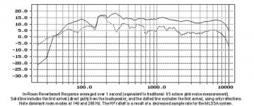
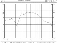
This is with the mic sitting at the sofa at the same position the listener's head is (before they bury it in there hands, of course), both speakers swept at the same time, same volume.
An externally hosted image should be here but it was not working when we last tested it.
Obviously, I have a little issue with room acoustics at about 60 Hz.
I did measure both speakers and they do perform almost identical.
If you look at a few posts back, I did a 3-D picture of the room layout. See post #58. The plot above was with the sofa against the wall and one speaker in the corner (first 3-D layout).
Eventually, we would like to rotate everything 90° counterclockwise when we get some more redecorating completed.
To get an idea of what the impact of those changes I moved everything in the room as we plan to put it and ran another plot from the head position at the sofa. Both speakers were jammed into the corners with them angled toward the listener (mic). This was the best performance. Moving the speakers away from the wall made the bass worse. Here is the plot with the speakers all the way in the corners (second 3-D layout):
An externally hosted image should be here but it was not working when we last tested it.
The bass is much better. However, what gives with the treble at 8,500 Hz?
Moving the speakers from the corner does not help the treble, incidentally.
I will try the idea of pulling the center stuffing panel out this weekend.
Last edited:
Thanks for posting the first curve - several things jump out at me:
1) The bass is essentially one note at 50 Hz, so it'll sound like a thud, not bass, and there are two huge suckouts at 100 and 200 Hz. This is the frequency range that gives music "support" - if a system is thin in this range, it'll sound like "no bass". The problem with "filling in a hole" with equalization is that it costs a lot of power and woofer excursion - better practice is removing the peaks, and letting everything else come down to average level.
2) What jumps out at me is the region from 700 Hz to 2 kHz is elevated 5 dB compared to the treble and much of the rest of the range. This is a crossover design error, and will dramatically affect the balance of the entire system. You don't have too little bass, your mids are too hot!
Beg, borrow, or steal a parametric equalizer, and set a 10 dB notch at 50 Hz, and pull down the region between 700 Hz and 2 kHz about 5 dB. Once you hear what a halfway flat system sounds like, you can get to work on the midrange crossover. The rise at HF, by the way, is caused by increasing directivity from the tweeter, and is normal - you can see the same thing happening with Ariel room response, shown below. Subjectively, the Ariel has a slightly "warm" balance, and sounds very smooth. That is designed in, since mid or HF emphasis is very rare in nature, and usually sounds like a recording artifact when you hear it.
Some people like artificial sound, but I don't, so I deliberately adjust the frequency balance to bias the response in the direction I want. A 1 to 2 dB tilt from 100 Hz to 10 kHz is a common practice in the industry, and sounds subjectively flat. Flat does not sound flat. What matters is subjective flatness, not what you see on the measurement.
P.S. By the way, professionals never measure the frequency response at 1 meter. I've been doing this since 1975, and I've never come across anyone in the industry measuring at 1 meter. The reason is simple: the wavefront hasn't fully "gelled" at that distance, and if the system is EQ'ed flat at 1 meter, it most assuredly will be wrong - sometimes very wrong - further out. In practice, 2 meters is a very common measuring distance, and the efficiency is back-calculated to the 1 meter distance - although the true Thiele/Small efficiency of the woofer gives more accurate results, since it's not affected by peaking elsewhere in the range.
To summarize, deal with the 50 Hz peak any way you can. Measure the port directly - is it tuned too high? Well, there's your answer. Otherwise, assuming the port is tuned to the correct frequency, you must physically move the speaker or apply EQ to get rid of the big peak.
The mids are way too hot, and stand out from the rest of the range, particularly the treble. Even your second curve shows the elevated region. This will not sound good, unless you're trying to replicate a JBL L100 or Klipsch Heresy, where the mid emphasis was a deliberate design feature.
Attachments
Last edited:
Thank you for your input.
I want to take one of these outside and perform an open-air sweep to see if I can get a true picture of the response of the cabinet without all of the room interference.
I'll put the mic out 2 meters or so as well.
I want to take one of these outside and perform an open-air sweep to see if I can get a true picture of the response of the cabinet without all of the room interference.
I'll put the mic out 2 meters or so as well.
Hi Loren42,
Working over the weekend on a speaker project – you must be an avid speaker builder !
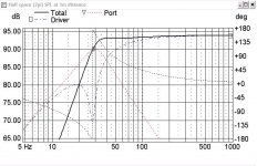
I’m not sure if I can be of help here, but I took the data you posted and entered it into LEAP5. As it turns out, Leap5 has a model of the JBL 2235H in its library of transducers, so it didn’t take long to run a simulation on your system. I noted in one of the pictures you posted, you were using a vacuum tube amplifier, with a power output of about 50 watts. I made the assumption that the output impedance of the amplifier plus the DC resistance of the Xover was about 1 ohm, which I included in the simulations.
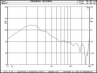
The enclosure volume in the first simulation (red curve) was fully stuffed with fiberglass stuffing material and as you can see from the attached, the response is reasonably flat, except for a very shallow roll-off below 100Hz, followed by the normal low frequency –3dB point at 32Hz.
For the second simulation, I reduced the amount of stuffing from 100% down to 30% resulting in the response shown by the blue curve. As you can see, this gave an increase in level of about 2dB at 40Hz.
Keeping the stuffing the same, I then ran a simulation with only one port having a diameter of 6”. The length of this port was adjusted to give the same tuning as with the 2 x 3.95” ports. The results of this simulation are shown by the green curve and as you can see, it pushes the response up just a little bit more at 40Hz.
For me, I often find that a small amount of bass boost like this sounds much more natural than a flat response in my listening environment.
Lastly, I note you said that you had installed a curtain of damping material in the enclosure. This reminded me of a comment made by Martin Colloms in his book High Performance Loudspeakers, where he described the measurements made on a 3rd order BP subwoofer with damping material that was not well secured. One of the responses was made with a swept sine wave and a second response made with an impulse response + FFT. Under normal circumstances, both measurements should appear the same, but in this particular case, they were very different, especially at frequencies in the range of 20Hz – 50Hz. The swept sine wave measurement showed an extended low frequency response, but the impulse response did not. The reason for this was said to be due to the swept response allowing the damping material to move more freely because of the long time it took to make the swept measurement, but the impulse response took very little time to measure and did not allow the material to move at very low frequencies. Colloms credited the publication of this phenomena to Fincham at KEF Electronics.
Hope some of this is of help to you and good luck over the weekend.
Regards
Peter
Working over the weekend on a speaker project – you must be an avid speaker builder !
I’m not sure if I can be of help here, but I took the data you posted and entered it into LEAP5. As it turns out, Leap5 has a model of the JBL 2235H in its library of transducers, so it didn’t take long to run a simulation on your system. I noted in one of the pictures you posted, you were using a vacuum tube amplifier, with a power output of about 50 watts. I made the assumption that the output impedance of the amplifier plus the DC resistance of the Xover was about 1 ohm, which I included in the simulations.
The enclosure volume in the first simulation (red curve) was fully stuffed with fiberglass stuffing material and as you can see from the attached, the response is reasonably flat, except for a very shallow roll-off below 100Hz, followed by the normal low frequency –3dB point at 32Hz.
For the second simulation, I reduced the amount of stuffing from 100% down to 30% resulting in the response shown by the blue curve. As you can see, this gave an increase in level of about 2dB at 40Hz.
Keeping the stuffing the same, I then ran a simulation with only one port having a diameter of 6”. The length of this port was adjusted to give the same tuning as with the 2 x 3.95” ports. The results of this simulation are shown by the green curve and as you can see, it pushes the response up just a little bit more at 40Hz.
For me, I often find that a small amount of bass boost like this sounds much more natural than a flat response in my listening environment.
Lastly, I note you said that you had installed a curtain of damping material in the enclosure. This reminded me of a comment made by Martin Colloms in his book High Performance Loudspeakers, where he described the measurements made on a 3rd order BP subwoofer with damping material that was not well secured. One of the responses was made with a swept sine wave and a second response made with an impulse response + FFT. Under normal circumstances, both measurements should appear the same, but in this particular case, they were very different, especially at frequencies in the range of 20Hz – 50Hz. The swept sine wave measurement showed an extended low frequency response, but the impulse response did not. The reason for this was said to be due to the swept response allowing the damping material to move more freely because of the long time it took to make the swept measurement, but the impulse response took very little time to measure and did not allow the material to move at very low frequencies. Colloms credited the publication of this phenomena to Fincham at KEF Electronics.
Hope some of this is of help to you and good luck over the weekend.
Regards
Peter
Attachments
Peter,
Thank you for running that analysis!
When you say 30% stuffing, how is that placed in the cabinet? Is that stapled on the walls or is that loose packed?
What happens when I substitute Acustastuff or even polyfill for fiberglass?
It would seem someone else I know pointed out that the LEAP crossover PDF I posted LEAP X-Over did not seem to match the models of the transducers I was using. He pointed out that the crossover, as simple as it was, seemed to tame a lot of the nasty anomalies that were present in the driver's response curves when compared to the published data from the manufactures.
Yes, I have spent a lot of time on this system. When things are not right it bugs me and I end up burning a lot of time trying to resolve it. It's frustrating at times (i.e., now), but rewarding when the victories appear.
My next magical act seems to be a transmission line enclosure. Although, I have no idea where I would put such a skyscraper. 😀
Thanks again.
Hi,
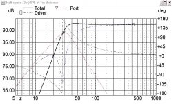
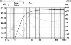
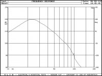
A friend of mine use two JBL 2235H as subs, enclosure about the same size as yours but tuned lower @23Hz. Last Saturday I did some measurements for comparison.
Attached pics in following order:
Simmed result 2Pi 28Hz tuning
Simmed result 2Pi 28Hz tuning , 1Ohm source
Simmed result 2Pi 23Hz tuning
Meauserments with active filter 80Hz, no EQ and subs only:
2235H 5” away from dustcap
Port contribution (5” distance)
Inside box
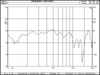
Listening position (disregard the 10Hz disturbance)
Quite good I’d say, room gain sum nicely with the falling slope ebs alignment.
I’d suggest a measurement out of your room, preferably outdoors to see the real response out of our design.
Now it seems like either some box issues or room issues that you need to compensate by corner placement. A 2335H in a 6cu ft box tuned to about 30Hz should do just fine imo. Also, try another amp to be sure.
A friend of mine use two JBL 2235H as subs, enclosure about the same size as yours but tuned lower @23Hz. Last Saturday I did some measurements for comparison.
Attached pics in following order:
Simmed result 2Pi 28Hz tuning
Simmed result 2Pi 28Hz tuning , 1Ohm source
Simmed result 2Pi 23Hz tuning
Meauserments with active filter 80Hz, no EQ and subs only:
2235H 5” away from dustcap
Port contribution (5” distance)
Inside box
Listening position (disregard the 10Hz disturbance)
Quite good I’d say, room gain sum nicely with the falling slope ebs alignment.
I’d suggest a measurement out of your room, preferably outdoors to see the real response out of our design.
Now it seems like either some box issues or room issues that you need to compensate by corner placement. A 2335H in a 6cu ft box tuned to about 30Hz should do just fine imo. Also, try another amp to be sure.
Attachments
If, as Lynn suggests, the problem is higher up, perhaps the problem lies with the crossover design; Did Madisound consider BSC in their design? I don't think Loren42 has posted his xover schematic?
If, as Lynn suggests, the problem is higher up, perhaps the problem lies with the crossover design; Did Madisound consider BSC in their design? I don't think Loren42 has posted his xover schematic?
I thought I did somewhere, but here it is again...
Leap Crossover PDF
When I asked Madisound about baffle step compensation (and I gave them the details of the cabinet), I was told that was beyond the scope of what they could do.
The mid response is pretty bad - I particularly dislike the twin peaks at 780 and 980 Hz. That would be quite objectionable on most program material. The crossover, as measured, is just plain wrong. As a start, why don't you bring down the mids by 3 to 5 dB, listening to pink-noise as you go?
One of my favorite subjective-tuning methods is to extend an L-pad control all the way out to the listening position, listen to pink-noise coming from one speaker only, and balance the system as close as I can to subjective flatness. I limit the balance sessions to no more than a minute or so, since listening to pink-noise, particularly on a rough speaker, is fatiguing and that, in turn, decreases acuity and ability to discriminate flat from rough. Turn the knob fairly quickly, listen, and try to aim for the sound of a waterfall. Stop when it sounds right. Don't touch it again until you measure the resistances on the control!
Once I've got the thing more or less lined up, then I measure the resistance on each side of the L-pad, and duplicate it with discrete resistors in the crossovers.
Don't be surprised if the two speakers want/need different amounts of midrange attenuation. Driver variations alone can account for 1 to 2 dB differences in efficiency. You don't have the luxury of matching drivers from 100 samples, as manufacturers do, so you have to make-do with the drivers you have, which are unlikely to match within 1/2 dB. What you want is subjectively flat response from each individual loudspeaker, and if the systems are really flat and well-balanced, a tight center image and exact phase match between the pair. But that takes good measuring gear and pretty flat overall response to even get there.
Last edited:
A 1 to 2 dB tilt from 100 Hz to 10 kHz is a common practice in the industry, and sounds subjectively flat. Flat does not sound flat. What matters is subjective flatness, not what you see on the measurement.
P.S. By the way, professionals never measure the frequency response at 1 meter.
Hi Lynn
Agreed with one caveat. I like to be down about 2 dB at 10 kHz and up about the same, maybe a little more at 20-30 Hz, but it's not a linear slope. The LF rise starts at about 200 Hz and the HF fall at about 2 kHz. Between 200 and 2 kHz I like to see it pretty flat. (This is in-room of course.)
Agreed on the 1 meter thing. A lot of people here get this wrong. Worse is the guys who measure a horn in the mouth. That's really ridiculous.
- Status
- Not open for further replies.
- Home
- Loudspeakers
- Multi-Way
- Why no Bass?