This circuit burns ~35mwatts of power, but most of it in the opamp even thou the load is only using a fraction of the power (.5ma). Most of the current (5ma) that goes into opamp V+ goes out the oamp ground. WTF? Am I doing something wrong or is LTspice. Or is this how much power this opamp actually wastes? The data sheet says Icc 1.4 to 2.5 ma at +/-15v rails so I was expecting quite a bit lower Icc than 4.5ma. does the Icc go up when Vcc goes down?
Attachments
No Icc stays fairly constant with Vcc. Just found the data sheet graph. but it shows around 1.5ma. why it maters: this is just a part of a guit pedal design. The rest of the circuit willl have about 10 opamps. That 3ma differnce adds up to about 300mw more power consumption making a 9v battery last a few hours. Plan B would be a power supply.
Thanks for your replies.
Thanks for your replies.
Last edited:
Compare with LT1057 which is broadly similar to TL072. The min voltage is 8V. The quiescent is 1.5mA in sim = 0.0015*9 = 13.5mW
There are much lower current devices available.
There are much lower current devices available.
Last edited:
R6 looks redundant - that's an unnecessary 4 mW right there. Has this been adapted from split supply by any chance?
Also, if the model says TL072, it may be modelling the current draw of a dual = 3.4 mA. Better take a look at the model to see what it does.
Is there any theory of operation for this circuit? I know a thing or two about (RF) AGCs but I can't say this one is too obvious to me.
Also, if the model says TL072, it may be modelling the current draw of a dual = 3.4 mA. Better take a look at the model to see what it does.
Is there any theory of operation for this circuit? I know a thing or two about (RF) AGCs but I can't say this one is too obvious to me.
The 10k is just a load for the sim, not sure exactly what this is driving but just ignore that. The data sheet says 1.5 ma per oamp so maybe the extra is just a sim thing.
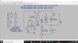
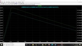
This is just the attack decay circuit for the compressor, the gain stege is a THAT VCA. This circuit charges and discharges the cap thru the pots and FETs. The FETs change there impedance with current greatly increasing the range of charge/discharge current.
I didn't read the other thread, but the required current for the cap decay 7s/V is 1uA, then for 7 ms/V it is 1 ma, the attack is shorter and requires more current when charging. Best is to reduce C a bit to keep currents low.
You can use C-MOS opamps with as little as 1uA supply current.https://www.analog.com/media/en/technical-documentation/data-sheets/600345fd.pdf and https://www.analog.com/media/en/technical-documentation/data-sheets/ADA4084-1_4084-2_4084-4.pdf for audio.
I would make proper current sources with MOSFET or FETs and cmos opamp which can be easily shut off and use lower ohms pots, you could also add the discharge current to the charge current to allow independent settings.
Last edited:
I had another look at your timing cap. I guess you want to use the 4305 or 4315
Charging current will be 3.5uA to 13mA. Your 1Mpot will burn out at this high current 13mA. A 1W pot of 1M will only carry 1mA, maybe a little more because it's log tapered.
The discharge current is 300nA to 18uA difficult too because of offset voltage/ leakage current.
Both problems can be cured with mosfet current sources. How to Build a Current Source Circuit
The discharge can use a current mirror on the +rail. Use the E- input of the VCA
The input voltage is provided by the pot no current in the wiper.
Last edited:
You realize that unless there's a source of 13000 volts somewhere there's never going to be 13mA flowing through the pot end-to-end? At the endstop true there's only 100 ohms to protect it, but at that point the wiper is probably on the metalization and the resistance is likely to be zero.Charging current will be 3.5uA to 13mA. Your 1Mpot will burn out at this high current 13mA
If not the track resistance will be a few k at most for a log pot, so the dissipation is very low in a 9V circuit.
Last edited:
Useful book, doesn't change the facts of the matter. I'd probably use a 1K resistor but it's going to be hard to destroy a 1M pot in this circuit.
CDDB, have a look at TL62 and perhaps the MC33178.. (Commonly used in MI pre-amps and processors back when I was designing such)
There are basically 3 factors that fail pots.
1. wear: the wiper scratches the resistive material after longer use and becomes intermittent.
2. heat: the indicated value (0.25W or so) rtefers to the power across the two endpoints. When a pot is used like in the OP circuit with the wiper shorting parts of the track, the power concentrates on the not shorted part, So when the value is 1k, only 1/1000 of the track is used with much lower allowed dissipation (a bit more then 1/1000 because of better cooling) The small area where the wiper touches gets hot and burns a little hole in the track
3. DC-current through the wiper: a reliability issue. Any dc-current will create chemical changes when two different materials touch each other. Cheap pots have a metal wiper and a carbon track. Electrolysis creates deposits on the surfaces. The more current the more is deposited. AC reverses the process each cycle. Buffering the wiper with an opamp has only the bias current flowing, almost nothing.
Last edited:
This circuit burns ~35mwatts of power, but most of it in the opamp even thou the load is only using a fraction of the power (.5ma). Most of the current (5ma) that goes into opamp V+ goes out the oamp ground. WTF? Am I doing something wrong or is LTspice. Or is this how much power this opamp actually wastes? The data sheet says Icc 1.4 to 2.5 ma at +/-15v rails so I was expecting quite a bit lower Icc than 4.5ma. does the Icc go up when Vcc goes down?
What is that circuit?
What is it supposed to do?
What´supposed to be at "In"?
Where is the output?
What´s biasing the different elements ?
I suppose you have DC at U3 output, why do you load it with a 10k resistor to ground?
Where are V1/V2/V3 in the schematic?
The People wants to know 😕
That's a recipe for very loud bangs and crackles - never route bias current from an opamp through a pot wiper unless its a FET opamp with only picoamps.3. DC-current through the wiper: a reliability issue. Any dc-current will create chemical changes when two different materials touch each other. Cheap pots have a metal wiper and a carbon track. Electrolysis creates deposits on the surfaces. The more current the more is deposited. AC reverses the process each cycle. Buffering the wiper with an opamp has only the bias current flowing, almost nothing.
As the wiper moves it will occasionally break circuit over the lumps and bumps and bits of dust - if you route bias current through this the opamp will immediately saturate to the rail generating perhaps 12V of transient (bias current must always flow)! Even if it doesn't saturate you can get very audible noise from this.
With a FET opamp the stray capacitance keeps the voltages under control for these brief periods.
No, here we adjust the charging current of a capacitor. there will be always a small C to ground to suppress any short time variations.
Anyway we talked about CMOS opamp having even less bias current 5pA than a fet .
You are right about audio circuits without another resistor to gnd
Anyway we talked about CMOS opamp having even less bias current 5pA than a fet .
You are right about audio circuits without another resistor to gnd
Last edited:
- Home
- Source & Line
- Analog Line Level
- Why is this oamp burning so much power?