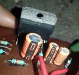
Can you post a schematic? This drawing doesn't mean a lot without a schematic diagram with pin names.
Jan
Jan
Compare your:

to "official"

you are missing mute and standby caps, but much worse shorting pins 5-6 and 10-11 for no good reason.
You are not showing a "proper" schematic but somenting that looks as if pulled from a low quality YT video, not the best source for anything.
Why did you choose and trust it on the first place?
ALWAYS follow the official Datasheet schematics, they always work.
Maybe somebody can improve them, no doubt, but they work as-is.
to "official"

you are missing mute and standby caps, but much worse shorting pins 5-6 and 10-11 for no good reason.
You are not showing a "proper" schematic but somenting that looks as if pulled from a low quality YT video, not the best source for anything.
Why did you choose and trust it on the first place?
ALWAYS follow the official Datasheet schematics, they always work.
Maybe somebody can improve them, no doubt, but they work as-is.
Thanks Mr. I will try thisPins 5 and 6 shorted together does not look correct the chip has a bootstrap pin that the cap connects to.
There are also a pair of 10uf caps on the mute and standby inputs.
Thanks Mr.
But can this sound so well if I put the mute and standby caps?Compare your:

to "official"

you are missing mute and standby caps, but much worse shorting pins 5-6 and 10-11 for no good reason.
You are not showing a "proper" schematic but somenting that looks as if pulled from a low quality YT video, not the best source for anything.
Why did you choose and trust it on the first place?
ALWAYS follow the official Datasheet schematics, they always work.
Maybe somebody can improve them, no doubt, but they work as-is.
Connect it exactly like the datasheet and try again.
Mind you, with only +/- 22 V rails it won´t put out much, don´t expect miracles.
Mind you, with only +/- 22 V rails it won´t put out much, don´t expect miracles.
What the datasheet suggests.
Many use it with +/-40V rails, a few daring souls up to +/-45 which is dangerous/unreliable in my mind; personally I use +/-35V and they "live forever" so I suggest the same.
Yours will work with +/-22V, but will not put out maximum power by any means.
Check the datasheet, there is a "Power vs rail voltage" graph, check it with whatever you use.
There was a very experienced Forum member, the lamented Enzo, who now and then answered with his "Enzo Truths" .
When people obsessed about some minor and typically inaudible detail, he answered: "the Amplifier is just that thingie between the Power Supply and the Speaker" 😉
Thanks Mr. for your concern... But again I installed the mute and standby circuit, but the ic is heating so much and am having some noise in the speaker
Follow the official schematic from tda7294 datasheet. Increase the input cap to 2.2uf, feedback & bootstrap cap to 100uf. It's a nice chip with lots of power, i recommend +/-30vDC with 4700-10000uf/rail reservoir capacitors.
(and don't forget to use insulators*)
Good luck!
(and don't forget to use insulators*)
Good luck!
Last edited:
Therefore i said: read the datasheet: it says you might need a Zobel RC with a power supply voltage lower than +/- 25V
- Home
- Amplifiers
- Chip Amps
- Why is my TDA7294 not sounding to my desired output on +-22v ? Even my TDA2050 mono amp is better than it, I used the shematic below
