Is this something to consider after how many years of acoustics and speakers and the relationships of things to quarter wavelengths, pipe closed end harmonics, thermo versions of ‘pipes’ as motor generators of a heated and cooled on a pipe at a point offset by 1/3 its end?
The AC cycle,(everything with odd numbered harmonics maybe?, the phase of an offset driver at 1/3 down a ‘pipe’ or the use of 1/3 the opposite sides pipe as the length of the otherside to tube with if the phase is to be such that it couples(or so it seems in almost anything i try to sim or build or both?
Its no coincidence right? Or is it just the result of the inevitable nostalgic but silly idea and no more than ‘cosine and sinewaves at intervals of 30/60/90 to pythagoreum in a rotating of 1/3,2/3, 3/3... a circle..?
I feel dumb asking this. As if its a well known thing and im kinda overthinking its relevance to an assumption the qw designs or half of a wave(?) or non of it, are the ideal ways to cut and apply (in 3rds, as an offset if wanted to get ‘extra, thats there anyhow, but looks like ‘extra’ if comparing wide to tall in a response in subwoofers?
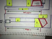
This idea might be best shown as ‘offset driver TL, and ‘compound horn’? One is 1/3 the other, and that results in a extension of the top area of BW it seems, and exactly how to donit hivers on the straight pipe sized and applied as 1/3.
this inside the speaker if a pipe, is also the ways to couple them within 270 degrees of the top section of the circles circumference.
I thihght that was obvious, but then i realized i was only used to umit, not so much that i had ever truely witnessed the use of another? My iffset drivers and paraflex, etc all get simmed. I never had ro ‘figurevout much of ‘why’ it was always in the right spot and thanks to David Mcbean, and /or Martin King, its pretty easy for anyone to do this?
But i just realized(?)!!!??
I have never ever looked at the other, or at the squiggly shape that shows up in the area of ‘junction’ in horn response...where two outputs or the dead end reflected of itself or seperates off the opposite side of a cone converge at or before exit?
Can i find these things by making them? And what will there be on a pressure gage and a mic, REW, and test tones specific to the pipe?
i have a lit of questions to which i intend to ‘look’. But where and what im
Not sure? But im going to start with thus OD TL... made to drag a mic and pressure sensor(?)around inside by a magnet on the other side of the lexan as shown
The AC cycle,(everything with odd numbered harmonics maybe?, the phase of an offset driver at 1/3 down a ‘pipe’ or the use of 1/3 the opposite sides pipe as the length of the otherside to tube with if the phase is to be such that it couples(or so it seems in almost anything i try to sim or build or both?
Its no coincidence right? Or is it just the result of the inevitable nostalgic but silly idea and no more than ‘cosine and sinewaves at intervals of 30/60/90 to pythagoreum in a rotating of 1/3,2/3, 3/3... a circle..?
I feel dumb asking this. As if its a well known thing and im kinda overthinking its relevance to an assumption the qw designs or half of a wave(?) or non of it, are the ideal ways to cut and apply (in 3rds, as an offset if wanted to get ‘extra, thats there anyhow, but looks like ‘extra’ if comparing wide to tall in a response in subwoofers?
This idea might be best shown as ‘offset driver TL, and ‘compound horn’? One is 1/3 the other, and that results in a extension of the top area of BW it seems, and exactly how to donit hivers on the straight pipe sized and applied as 1/3.
this inside the speaker if a pipe, is also the ways to couple them within 270 degrees of the top section of the circles circumference.
I thihght that was obvious, but then i realized i was only used to umit, not so much that i had ever truely witnessed the use of another? My iffset drivers and paraflex, etc all get simmed. I never had ro ‘figurevout much of ‘why’ it was always in the right spot and thanks to David Mcbean, and /or Martin King, its pretty easy for anyone to do this?
But i just realized(?)!!!??
I have never ever looked at the other, or at the squiggly shape that shows up in the area of ‘junction’ in horn response...where two outputs or the dead end reflected of itself or seperates off the opposite side of a cone converge at or before exit?
Can i find these things by making them? And what will there be on a pressure gage and a mic, REW, and test tones specific to the pipe?
i have a lit of questions to which i intend to ‘look’. But where and what im
Not sure? But im going to start with thus OD TL... made to drag a mic and pressure sensor(?)around inside by a magnet on the other side of the lexan as shown
Attachments
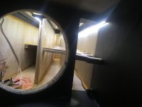
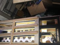
Heres what im using to ‘screw up’ an already established offset pipe that should represent itself as simmed, or very close to what will be the standard of reference for things to be once changed(see the ‘bypass’ in the first and middle segments of the pipe (not the one beside it, (above in thumbnail it) thats next on the menu of changes to observe..
Attachments
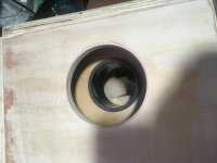
This 3” sched40 with a threaded bung and cap wimhich is easily accessd and open/ shut fully or (later) given layered discs you might see in a spark arrestor type of muffler ‘suppertrapp’ formerly in ‘ktm’ speak to me otherwise..
But also, this removes the stub, creates a stepped taper as two segment pipeoff the driver-at end instead.. and much more to come if i find things worth ‘studying, learning real, no more cheating by reading and borrowing the experience of others(many of which are here in this place and the hours and hours ive spent reading your typed wordsarchives and past threads and links and pictures(thank you for that btw!!)
But also, this removes the stub, creates a stepped taper as two segment pipeoff the driver-at end instead.. and much more to come if i find things worth ‘studying, learning real, no more cheating by reading and borrowing the experience of others(many of which are here in this place and the hours and hours ive spent reading your typed wordsarchives and past threads and links and pictures(thank you for that btw!!)
Attachments
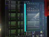
Sim, and Dayton rss265ho4 and no rear chamber, path is ‘zero’.
Attachments
Last edited:
So, im assuming (after a confirmation of the build to sim in REW nd with the datsv3 ) that im gonna go searching for landmarks inside this. And by a yet to be determined?(?) pressure transducer (?) or possibly a cheap manometer from amazons offbrand electrics section and the UMM6 in REw, with individual tones(sine wave or ?) im Gonna locate some things? And by opening the bypass they might be gone, relocated, list or gained dB or a pressure null or peak??? But, what and where might not be exactly as im assming? And kibd of why im asking 🙂 what could be ? What other things could i create here while still not sealed up and glue cured might i wanna make possible in this lab rat?
I have an interesting chart of a variety of ‘stuffing and isulating types of damping with some tech data to confirm in reference to the standard polyfil from her side of the beds pillow lol🙂
I have an interesting chart of a variety of ‘stuffing and isulating types of damping with some tech data to confirm in reference to the standard polyfil from her side of the beds pillow lol🙂
- Home
- Loudspeakers
- Subwoofers
- Why is everything a cycle of 3? Or is it?