Why is a square so wrong? I mean if there's the back sides of the drivers, a port tube, a crossover, a terminal cup, whatever sonic padding or fill you use, corner blocks, bracing, wire and whatever else.. really how much of a prefect square is left after all that?
Another question, how far can you offset a tweeter from the woofer? it seams a lot of folks go .75 to 1 inch. Is that the max or will it depend on the dia of the woofer? Can tweeter for a 7" woofer be offset further then one for 5" woofer?
Thanks for any info TY.
Another question, how far can you offset a tweeter from the woofer? it seams a lot of folks go .75 to 1 inch. Is that the max or will it depend on the dia of the woofer? Can tweeter for a 7" woofer be offset further then one for 5" woofer?
Thanks for any info TY.
It is important to avoid standing waves inside an enclosure, if the side to side, top to bottom and front to back dimensions are all the same a standing wave is virtually guaranteed. At the standing wave frequency you will often get a peak or even a dip in response and almost always a slow stop and start for signals at that frequency. The sonic result might be described as a "hang", "hollow sound", "boxy sound" or "peaky".
Changing the shape of the enclosure will only change the frequency of the standing wave. Adding fiber stuffing in the middle of the enclosure is the best way to mitigate the standing waves.
MJK said:Changing the shape of the enclosure will only change the frequency of the standing wave. Adding fiber stuffing in the middle of the enclosure is the best way to mitigate the standing waves.
Interesting! where there's a will there's a way.
what about the tweeter offset?
i would say, making the enclosure so small, that no standing wave can occur, is even better. with low qts, such enclosures are possible. standing wave occurs when the internal dimension is 1/2 wavelength long. if you cross below that frequency, the standing waves will be out of the passband of the driver.
The idea here is too make each dimension different so that any standing waves of any two dimensions are not harmonically related. I can never remember if the cube root of three or 3 times the square root of 2 is considered the best ratio.MJK said:Changing the shape of the enclosure will only change the frequency of the standing wave. Adding fiber stuffing in the middle of the enclosure is the best way to mitigate the standing waves.
Fiber padding increases the apparent length of any internal dimension, the fiber stuffing has poor absorptive properties so does little to reduce standing waves. Non acoustically reflective linings on the interior walls, wool etc are better.
Tweeter offset: Most tweeters have a voice coil much closer to the front of he driver than midrange drivers. By recessing the tweeter it tends to equalize the acoustic center of the drivers and equalize acoustic arrival times at the listing position. Offset also affects lobing, lobes are nearly inevitable when more than one driver contributes to the sound output at or near the crossover frequency.
Looking at the outside of the box, there will be diffraction effects at the box edges.
square means all diffactions occuring at the same wavelength.
It's good to mix that up.
Curved edges help.
Tweeter offset is to align time/phase with the midrange/lower frequency driver.
Offset effects phase, and thus involves the crossover.
The offset should match up with the lower freq. driver acoustic center.
Could somebody explain phase to me - I can understand aligning time but what is phase. This also applies to amplifiers with a phase shift from 20Hz to 20KHz!
In a capacitor current leads voltage by 90 degrees, this is a phase shift, in an inductor the opposite is true, voltage leads current. In a driver the cone may take a little time (due to mass) to react to the voltage waveform causing a phase lag. This lag increases as a percentage as the frequency goes up. Because drivers have phase shift it is often the case that one driver's polarity needs to be inverted in a two way design to cause the signals to sum correctly at the crossover frequency. This stuff is well understood, but it isn't simple and is one reason why newbies are usually encouraged to build a kit as their first project.jkeny said:Could somebody explain phase to me - I can understand aligning time but what is phase. This also applies to amplifiers with a phase shift from 20Hz to 20KHz!
Rather than ask lots of follow on questions, is there a good on-line or print explanation of this?
This may be a good place to startjkeny said:Rather than ask lots of follow on questions, is there a good on-line or print explanation of this?
result.http://ldsg.snippets.org/
There is an awful lot of data here, more about drivers than electronics. Once through this the electronics can be dealt with separately. Although it's important to understand that the drives and crossovers form a network that works together to accomplish the end
poobah said:jkeny,
Also keep in mind that phase and time are different ways of describing the same thing.
Yes, I had an inkling that this was the case but what is the relation between time & phase?
When an amp is said to have a 20 degree phase shift what does this mean? Is this good/bad or about right? Would 0 degree be better? Is this possible?
It is not that THAT complicated...
Let's say you're talking a phase "lag" of 90 degrees:
There are 360 degrees in a circle... (CYCLE).
Now let's say that we are talking about a 100 Hz sine wave. 100 CYCLES PER SECOND.
SO:
1 second / [100 CYCLES per SECOND] = 0.01 SECONDS per CYCLE
Now... 90 / 360 = 0.25
So:
0.25 CYCLES X 0.01 SECONDS per CYCLE = 0.0025 SECONDS
This means that a 100 Hz Sine... lagging 90 degrees is actually 0.0025 seconds "late".
Phase refers to the "frequency domain". In a certain sense, it is dimensionless. Dawn, noon, dusk and midnight (phase) would mean the same thing... regardless of what planet you were standing on.
On the other hand... if you wanted the "time", you would have to know how fast the planet spins (frequency).
🙂
When an amp is said to have a 20 degree phase shift what does this mean? Is this good/bad or about right?
Hi jkeny,
Here is a good paper dealing with your subject:
http://users.ece.gatech.edu/~mleach/papers/phasedist.pdf
b
This isn't quite right. In the case of a driver, when voltage, current and acoustic output all align, the signals are in phase. It is possible to cause a delay of all three and they would still be in phase. It is when one or more of the three doesn't align with the others that there is a phase error.poobah said:<snip>
This means that a 100 Hz Sine... lagging 90 degrees is actually 0.0025 seconds "late".
<snip>
🙂
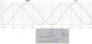
Attached is a very simple circuit showing the relationship between Voltage and current across an inductor at 1KHz. These signals are not in phase.
Attachments
If you mounted the driver in the center of the cube that would be one step away from the worst possible encolsure shape (other than no baffle at all): a cylinder with the speaker mounted in the center of one of the circular faces. Then again, the cylindrical wall is extremely strong and stiff compared to a flat face...The
In reply to putting in stuffing: Where there are parrallel walls, there is a standing wave. Stuffing can reduce it, but, so long as sound can be transmitted (I.E. there is anything other than a total vacuum in the enclosure) there will be some sort of standing wave. If you use significantly different types/densities of stuffing materials placed in stratigic positions, the standing wave can be greatly reduced, but that's different than simply loosely filling the whole cabinet with polyester or fiberglass etc.
Not only is having equal distances between the sides bad in that the standing waves will all be at the same frequencies, but also, the walls will also all be resonating at their (different than the wave in the air in the box) same frequency also. THAT issue can be more easily addressed however, by simply placing braces at different irregular locations to breakup the resonances into different frequencies (preferably not even multiples of each other).
In the case where the cube is less than 1/2 the wavelength (as mentioned by a previous poster) above which the speaker has no significant output, as in a subwoofer, then a cube is probably the ideal shape (next to a sphere), other than, perhaps, simply mounting the subwoofer in the floor/wall/cieling in the corner of the room...
- Status
- Not open for further replies.
- Home
- Loudspeakers
- Multi-Way
- why is a square shape enclosure such a "no, no"