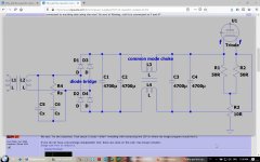
The caps and choke are a tank circuit that resonate on diode switching. Reduce the inductance (choke) and/or add resistance, or use slower diodes.
I am not sure that there is a need in common mode choke inside C-filter at all. It seems from this example that it make things worse but not better.
If there is a strong need - several small R (0.1R) may help to reduce effect (I mean CRCRC filter). If voltage drop becames large - it may use Shottky diodes (but ringing will rise).
If there is a strong need - several small R (0.1R) may help to reduce effect (I mean CRCRC filter). If voltage drop becames large - it may use Shottky diodes (but ringing will rise).
Last edited:
I set the camera resolution to the lowest size possible to begin with, and if still too big, open it in venerable but still useful IRFANVIEW (it runs on my W7 computer, so it mustbrun anywhere) and on the Image menu on top choose Resize/Resample
Usually "Half" does the trick but if necessary is repeated.
Then save then processed image for uploading to Forum.
Also if useful area is just part of the full image, you can select the interesting part and "crop" the image, deleting unnecesary garbage around.
IrfanView - Official Homepage - One of the Most Popular Viewers Worldwide
SIMPLEST yet powerful image processing.
Tried already 0.1 Ohm 5 W in positive and negative leg as well as 0.1 Ohm before and after the choke, it is not enough, and this is already too much voltage drop, therefore dead end.Such a count of large capacitors definitely wan't some R between them. For about 0.1 Ohm 5 W. It have to slow-down that ringing.
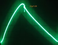
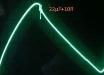
And I'm not sure if you tried low-R high-C RC-snubber (for example 5R 2.2uF)?
The Cx=10nF, Cs=680nF Rs=150R are from a source that showed that it works perfectly for diode bridge...I know now it doesn't work in my case and that your suggestions are much better, the tendency goes toward 5R 22µF or more, I will try lower R next. Thank you for pointing that out to me.Vovk Z said:Optimal Rs is somewere near a load resistance value. Your load is about several Ohms so Rs have to be about that.alujoe2 said:Quote:
Originally Posted by alujoe2 View Post
Attached the photo from Cx=10nF, Cs=680nF Rs=150R and there is only one photo as there is again no difference w/w.o. snubber
Yes, that is the correct answer 🙂! The resonance is much bigger than the diode ringing, therefore I couldn't see any changes.The caps and choke are a tank circuit that resonate on diode switching.
I don't know slower diodes than standard silicon diode bridge like KBPC3510. Making it slower by putting 10nF across them did nothing, reducing the CMC from 30 mH to 5 mH did almost nothing and adding 0.1 R at different places didn't help either. Therefore I removed the CMC, although it worked well when I initially tried it powered from a lab supply.Reduce the inductance (choke) and/or add resistance, or use slower diodes.
It seems we have given up on finding the cause, and resort to trying again and again things that were shown not to work.
Looking for keys under the lamp post?
Wish you luck,
Jan
Looking for keys under the lamp post?
Wish you luck,
Jan
No Load? What then?
BTW. in your Circuit from Post no.32 I can't find any 15MFD Cap.. So do I watch the wrong movie?
And then placing a 3 Ohm ressitor to GND or 5 Ohm is good as well for 10Volts & 3,5 amp. Check Ripple. 25mv - 100 mv should be OK.
How does it look like, could it be that the Transformer is overloaded.
BTW the diodes you choose need to be sinked to get that 8 AMPS, test them when Power is on with a thermometer for heat.
I lately used that kind on a motor control, and those Values were 12 A at 200 Volts, applying 12 volts with 4Amps got them smoking.. this just beside all the others.
Hope I could help at least something..
Have you tried the way of diconnecting all the load of your PSU after that 15MF Cap?I tried :
10nF across the diodes
Cs=1nF Rs=1k
Cx=10n Cs=200n Rs=2k potentiometer, max. 6cm wires
Cx=200n Cs=100n Rs=2k potentiometer, max. 6cm wires
Cs=470nF Rs=5
Cs=470nF Rs=10
Cs=940nF Rs=5
Cs=940nF Rs=10
...absolutely no change...
BTW. in your Circuit from Post no.32 I can't find any 15MFD Cap.. So do I watch the wrong movie?
And then placing a 3 Ohm ressitor to GND or 5 Ohm is good as well for 10Volts & 3,5 amp. Check Ripple. 25mv - 100 mv should be OK.
How does it look like, could it be that the Transformer is overloaded.
BTW the diodes you choose need to be sinked to get that 8 AMPS, test them when Power is on with a thermometer for heat.
I lately used that kind on a motor control, and those Values were 12 A at 200 Volts, applying 12 volts with 4Amps got them smoking.. this just beside all the others.
Hope I could help at least something..
Attachments
Last edited:
Such a snubber "Cx=10nF, Cs=680nF Rs=150R" will be ok for high voltage supply.
"although it worked well when I initially tried it powered from a lab supply." - of cause it worked well at direct current. It doesn't has a possibility to show its nature 🙂
The resonating LC-circuit will make a large trancient at DC (when powered) but will make a resonance at AC.
"although it worked well when I initially tried it powered from a lab supply." - of cause it worked well at direct current. It doesn't has a possibility to show its nature 🙂
The resonating LC-circuit will make a large trancient at DC (when powered) but will make a resonance at AC.
Last edited:
My 5 Cents
@alujoe2
How do you connect all support wires?
Is this Soldering, or using Plugs or screwing it to the PCB?
How are these connected?
I for one, Screw almost all wires from and to PCB as well as output to speakers. PSU GND and so on.
Sometime ago I was measuring with the Scope Frequency Responce on one of my Amps..
While I measured I had to see increased DC output at the DVM from usally 4millivots up to almost 200 Millivolts on speaker Terminals, which holds the dummy load.
Shutting down measuring, removing Input cable. Shunt the input to GND, and restart the amp. and it went straight up to 200mv..
To tell a rather long story in short, last it was the Cable which connected RE to the board. No, it was bad MANUFACTURING from my side.When screwed the Soder Lug to the 200WATT Resistor, it had a small portion of Isolation from the wire in between the Bolt and the Female part on that Screw thightened also.
So this small piecce of plastic generated 197millivolts DC at the output on that amp. Removing the WIRE and removing that little piece of Isolation from that solder lug, back to 3mv again..
About blowing a 15MF Cap..
I recently build a new PSU board with 2 - 22'000 ufd caps at 40 volts. For Dual Rail Voltages - knowing it would be more than 40 Volts on the caps while no LOAD.. No worries any good quality Cap can handle 10% overcharge..as soon the Circuit is uner load it will be a mere of 37 volts so no danger for the caps in the long run.
Two coils of 30-0-30 with a 350 VAC toroidal Transformer.. Two 25 Amps 200 volts Bridges.. so after Switching on. may 5 seconds after that main fuse 15 Amp at my Power connector 220V flew out..
Reseting that Fuse, plugging in a voltmeter showed that instead of 42 Volts unloaded at the end of PSU I could measure only 9Volts +.. But V- was -42.
Then a big bang and both BRIDGES EXPLODED.
Removing PSU Circuit from Transformer and Measured AC - all correct.
finally Because of bad markings on the capacitors, I screwed that 22'000ufd Cap - the positive one - the wrong way into that circuit board.
Cap was cold, and that with 42 volts the wrong way applied to if for more than all together 20 seconds. But both Bridged were toast. Security Resistors were toast.
But in your case the cap was in there before you changed diodes.
Diodes didn't blew, so my understanding of the problem is that the cap was OLD and may degraded. And therefore blew up. sometimes placing fast Switching diodes for a 50hz don't match, even those are build for this, but not for 50 Hz those are build for 20KHz up
So at 50hz those diodes will get hot and then eventually let AC PASS into the CAP, which in Reverse may can take 10% of the RATE DC VOLTAGE.. Bang..
Have you crossed each of the diodes in your circuit directly with .022ufd Cathode Anode, this will help reduce 50 hz noise and ripple as well not much but better than nothing,. Use CERAMICS for that.
More in my prior Post:
Test that Transformer Winding if it can keep up with that Capacitive load you are drawing from it.
Then also BYPASS these 4700 CAPS with 0.22ufd to cutoff the high frequenceys.. again it isn't the cure for it. but it also helps to decrease ringing if it comes from PSU-
Last but not least check it helps if you are using a 0.1ufd cap from Ground of Filament to GND of the AMP.. I'm not a Valve specialist.. it may helps, may not..
Again my first thought goes to that Transformer where you get the juice from for supply voltage..
BTW I agree with those who complained about that Picture of you even it wasn't a problem for me to open straight. Set open ZIP FILES with either Explorer or Firefox or whatever browser you use, and then the regular fotoprogram.. I use windows 10 Enterprise LTSB. Adding Photo viewer which MICROSOFT has taken out of Windows 10, will do Wonders in watching zipped Pic. But I aree with PRR for a two color PIC is no need to use 65K colors Quality even if it looks good..
Enjoy Sunday, and time will tell and I'm sure you will find that part which makes the problem.
Regards Chris
Thank You, if you read post #41 and/or #44 you would know that I have the keys already 😉.It seems we have given up on finding the cause, and resort to trying again and again things that were shown not to work.
Looking for keys under the lamp post?
Wish you luck,
Jan
The 15 mF is dead and I didn't have spare part, therefore I replaced it with two 4m7. Thank you for the interesting report.hpro said:Have you tried the way of diconnecting all the load of your PSU after that 15MF Cap?
BTW. in your Circuit from Post no.32 I can't find any 15MFD Cap.. So do I watch the wrong movie?
The interesting thing is, that the 15 mF blew, the following 2x 4m7 not, which IMHO proofs, that I didn't reverse polarity. But that 15 mF is history, the ringing was solved by cbdb in #41 and Vovk Z pointed me to the correct snubber values (3-5 ohm + 22-44 µF works).hpro said:But in your case the cap was in there before you changed diodes.
Diodes didn't blew, so my understanding of the problem is that the cap was OLD and may degraded. And therefore blew up.
In the moment I am trying to find a way to lower the hum/noise without dropping the voltage 😀.
Sorry I should have been more explicit - "worked well" means the CMC worked well for reducing the ripple of the lab-supply. Thank you for your informative posts.Vovk Z said:Such a snubber "Cx=10nF, Cs=680nF Rs=150R" will be ok for high voltage supply.
"although it worked well when I initially tried it powered from a lab supply." - of cause it worked well at direct current. It doesn't has a possibility to show its nature
The resonating LC-circuit will make a large trancient at DC (when powered) but will make a resonance at AC.
At least 3 of the famous gurus use it for that application, therefore I tried it.N101N said:I would not use a common mode choke in that position.
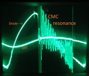
In the following pictures the CMC is wired as choke.
You deserve more than one 😀.I am glad that I was helpful. It is interesting to look at a new oscillogram.
An old image for convinience, Common Mode Choke: CMC.jpg
The new photos are done with these settings, Diode is 100mV, OPT is 5mV / division, the CMC wired as choke.
Are you satisfied with the damping or should I try something else ?
Attachments
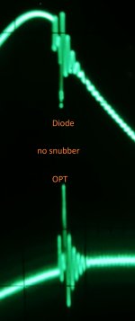

- unfortunately - not. 🙁Are you satisfied with the damping or should I try something else ?
There are several things that disturb me:
1) Common mode choke must not work as (good reliable) inductor (with large enough current). It can work as inductor only with a 10-100 times smaller than rated current (because of saturation).
2) I don't see an effect from this CMC-inductor. If it works - the ripple amplitude must lower (at least a bit). But I don't see that. It may be becouse of p.1).
3) If that additional inductor doesn't work but still make things worse (a bit) - then I don't see a reason to leave it. May be it is reasonable to get rid of it.
4) There is still at least 2 periods of that parasitic resonance (I may wrong). But good RC-snubber work mean one (no more than 1) period of parasitic ripple.
5) There is still parasitic ripple at OPT. This is clear indicator that something still is wrong.
I can't surely say what exact to do, but I would get rid of inductor, or I would search for good inductor for that place. As you see, CLC-filter is not an easy thing. Not any inductor will help.
There is some minimum inductance value (for specified load current) that make LC filter stable. If inductance is lower such value - we may have a resonance (and we see this).
I made some quick calculations. For 2x4700 uF capacity after L, the L have to have at least 1 mH at load current.
Last edited:
I totally agree on pt. 1 to 3 therefore I tried choke 10 mH / 6A rating.Vovk Z said:- unfortunately - not.Quote:
Are you satisfied with the damping or should I try something else ?
There are several things that disturb me:
1) Common mode choke must not work as (good reliable) inductor (with large enough current). It can work as inductor only with a 10-100 times smaller than rated current (because of saturation).
2) I don't see an effect from this CMC-inductor. If it works - the ripple amplitude must lower (at least a bit). But I don't see that. It may be becouse of p.1).
3) If that additional inductor doesn't work but still make things worse (a bit) - then I don't see a reason to leave it. May be it is reasonable to get rid of it.
4) There is still at least 2 periods of that parasitic resonance (I may wrong). But good RC-snubber work mean one (no more than 1) period of parasitic ripple.
5) There is still parasitic ripple at OPT. This is clear indicator that something still is wrong.
I can't surely say what exact to do, but I would get rid of inductor, or I would search for good inductor for that place. As you see, CLC-filter is not an easy thing. Not any inductor will help.
There is some minimum inductance value (for specified load current) that make LC filter stable. If inductance is lower such value - we may have a resonance (and we see this).
I made some quick calculations. For 2x4700 uF capacity after L, the L have to have at least 1 mH at load current.
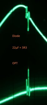
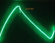
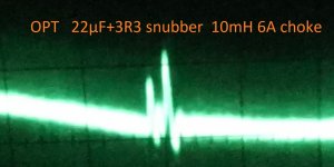
The snubber and/or the choke reduce a little bit the spike, the choke has hardly an effect on the size of the hum.
I hope you can see something on the close up picture (your pt. 4).
I agree on pt.5, please keep in mind there are three power supplies in action. One is the heater, two is the HV (UF5408 diodes, two in series, I can only measure up to 300V and this is 980 V) and three is the negative bias supply (UF4007 diodes) and looks more or less clean. The UF diodes are 'ultra fast, slow recovery' type.
Attachments


Brief observation (I'll add later something if will see):
1) parasitic ripple on OPT output doesn't change much with this snubber presence. This mean that source of this ringing may be somewere else. Is there a snubber in high-voltage power? What is a level of pulsation on high-voltage power? Etc. I think you have to explore all power supplies in the same way.
1) parasitic ripple on OPT output doesn't change much with this snubber presence. This mean that source of this ringing may be somewere else. Is there a snubber in high-voltage power? What is a level of pulsation on high-voltage power? Etc. I think you have to explore all power supplies in the same way.
If you can't measure HV-supply in direct way, just add some snubber there, and watch OPT output. For example 100-470 R 0.1 uF.
There are indirect ways to look at HV voltage (High-frequency CR filter, so you'll see only high frequency portion of voltage).
There are indirect ways to look at HV voltage (High-frequency CR filter, so you'll see only high frequency portion of voltage).
Last edited:
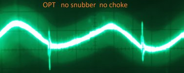
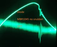
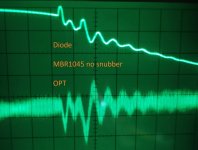
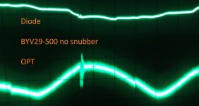
I tried MBR1045 and BYV29-500 instead of KBPC3510. Please look at the photos.Brief observation (I'll add later something if will see):
1) parasitic ripple on OPT output doesn't change much with this snubber presence. This mean that source of this ringing may be somewere else. Is there a snubber in high-voltage power? What is a level of pulsation on high-voltage power? Etc. I think you have to explore all power supplies in the same way.
IMHO the MBR1045 is as bad as the KBPC3510, the BYV29-500 looks promising and I can search now the next problem (HV I suspect).
How can I stop the high frequency oscillations(?) that are shown in the OPT ? Can I use a 330R and wrap some turns around it and put it at the anode or is there a better way ?
How many Hz for the f3dB of the CR-filter ? Will try the HV snubber.If you can't measure HV-supply in direct way, just add some snubber there, and watch OPT output. For example 100-470 R 0.1 uF.
There are indirect ways to look at HV voltage (High-frequency CR filter, so you'll see only high frequency portion of voltage).
Attachments
"How many Hz for the f3dB of the CR-filter ? Will try the HV snubber."
- at least two orders higher than mains frequency I think. Somewere close to this parasitic ripple frequency (I don't see time/frequency). So somewere higher 5-10 kHz.
"Can I use a 330R and wrap some turns around it and put it at the anode or is there a better way ?"
- it is not to me, unfortunately. I wan't say anything about anode ciircuits. (I am totally solid-state man).
I think the same parasitic ringing is present (has to be present) on all secondaries. And HV usually have the most short path to output (I mean has the lowest PSRR for this). So snubber on HV supply has to have the largest impact.
But if there are, for example, three secondary windings - you have to put snubbers at least at two of them.
If there are two secondaries - you may need either one snubber or two snubbers (on both second. W.).
Be careful with HV DC voltage. I was caught by 450 VDC once - it was one of the most dangerous moments in my life (I had some problem with my arm for about 2-3 years. Now it is ok).
BYV29-500 looks like good enough for this place in your setup. Some similar diode type has to be ok for HV too (taking into consideration higher rated voltage). I don't know what you use there.
Last edited:
- Home
- Amplifiers
- Power Supplies
- Why gets the capacitor cooked ?