That definitely looks like diode switch-off. You mention OPT, what is that?
It looks different with different caps because the switch-off point & current is different, this is expected but the cap is not the cause of it.
What you can do is try to keep that switching localized to the supply. That means that you have direct wiring from bridge + to cap + and from bridge - to cap minus. Nothing else should share this wiring.
Then you run again separate wires from cap + to your amp, and from cap - to your amp. In other words, consider the cap as the supply. You mentioned DHT so I guess the heater supply is connected to your cathode somewhere. Make sure your heater wire runs two separate wires to the heater, and connect to the cathode directly at the cathode. Don't share this wiring with anything else.
Jan
OPT = Output Transformer perhaps?You mention OPT, what is that?
Can you give us some indication of units of measurement?
Are we looking at tens of uV, mV, V...? It's hard to tell how bad a problem it is without a scale of magnitude to go with the images.
+1 to was said by previous orators and I can add one more idea: I had some strange similar noise, sincronized with 50/100 Hz when old film Rifa X2 caps in my Tektronix 2465A went bad.
Thank you for your valuable suggestions !
I could live with that explanation, BUT AFAIK it is accepted that standard silicon diode bridge has severe ringing. I think the pictures in my last post show this as well.
If ringing is a fact I should be able to change it by using 'standard' snubber values and hopefully eliminate it with optimized values. What confuses me a lot is that I cannot get any reaction to the snubbers I tried.
When I tried the BYV29-500 the ringing was a lot less, therefore I think it is valid to say there is a lot of ringing that could potentionally be damped by a snubber.
Thank you Jan.That definitely looks like diode switch-off. You mention OPT, what is that?
OPT= OutPut Transformer
DHT= Directly Heated Triode
Anything on the heater shows up on the loudspeaker.
It is exactly like that, the first cap is sitting right on the +/- terminals and from there with twisted pairs to the common mode choke, the next caps and the heater.It looks different with different caps because the switch-off point & current is different, this is expected but the cap is not the cause of it.
What you can do is try to keep that switching localized to the supply. That means that you have direct wiring from bridge + to cap + and from bridge - to cap minus. Nothing else should share this wiring.
Then you run again separate wires from cap + to your amp, and from cap - to your amp. In other words, consider the cap as the supply. You mentioned DHT so I guess the heater supply is connected to your cathode somewhere. Make sure your heater wire runs two separate wires to the heater, and connect to the cathode directly at the cathode. Don't share this wiring with anything else.
Jan
@avtech23 ...tens of mV, loud enough to be audible.
Still hoping somebody has some (in my case) working numbers for a snubber for a standard diode bridge....
OPT = Output Transformer perhaps?
I thought so but couldn't jive that with ringing on the power supply. I guess he measured at the output.
I still think it is a grounding issue, I mean the ringing is real but where does it come from.
BTW, you say it is audible, that must be the hum. The ringing probably isn't. How does it sound, like a mains hum with some harsh overtones?
Did you measure with the scope gnd clip disconnected?
Jan
Actually, thinking about it, if you measure the same at the OPT output side, that's the best indication that it is a grounding issue. There's no way this 'signal' could go through an OPT and come out at the end the same level and shape.
Jan
Jan
Thank you for your valuable suggestions !
I could live with that explanation, BUT AFAIK it is accepted that standard silicon diode bridge has severe ringing. I think the pictures in my last post show this as well.
If ringing is a fact I should be able to change it by using 'standard' snubber values and hopefully eliminate it with optimized values. What confuses me a lot is that I cannot get any reaction to the snubbers I tried.
When I tried the BYV29-500 the ringing was a lot less, therefore I think it is valid to say there is a lot of ringing that could potentionally be damped by a snubber.
Thank you Jan.
OPT= OutPut Transformer
DHT= Directly Heated Triode
Anything on the heater shows up on the loudspeaker.
It is exactly like that, the first cap is sitting right on the +/- terminals and from there with twisted pairs to the common mode choke, the next caps and the heater.
@avtech23 ...tens of mV, loud enough to be audible.
Still hoping somebody has some (in my case) working numbers for a snubber for a standard diode bridge....
The snubber value depends on the transformer secondary. See Mark Johnson's Quasimodo test jig for simple snubber value determination:
Simple, no-math transformer snubber using Quasimodo test-jig
As Jan mentioned, if you are investigating the output of the heater power supply, you need to scope it at the supply output. Scoping it at the OPT does not exclude other sources that may be causing the ripple and ringing.
Also as Jan mentioned, if you are hearing noise out of your OPT and speakers it is probably hum. Tens of mV of noise from an amplifier output is a lot.
That can be caused by wiring layout and large loop areas, arrangement of transformers and chokes, grounding arrangement, layout of components, not enough filtering in power supplies (not just filaments but also B+, bias).
Single ended amplifiers need low ripple power supplies.
I am not sure what exactly you mean with power supply, I am talking heater supply not HV.I thought so but couldn't jive that with ringing on the power supply.
IMHO changing from KBPC3510 to BYV29-500 clearly demonstrated that the KBPC3510 is the one to blame 😕.I still think it is a grounding issue, I mean the ringing is real but where does it come from.
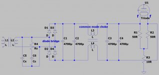
The secondary for the heater goes with twisted wires to the diode bridge. Right on top of the diode bridge was the 15mF cap(now 2x 4m7), from there with twisted wires to the common mode choke to 2x 4m7 and from there to the heater terminals of the 845. Both heater terminals connected using 50R to create artifical cathode at the connection, from there via 10 R to GND.
Yes, I agree.BTW, you say it is audible, that must be the hum. The ringing probably isn't. How does it sound, like a mains hum with some harsh overtones?
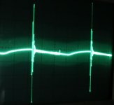
The spikes of the ringing are MUCH higher than the ripple voltage.
Both probes attached to +/- of the diode bridge. The differential between the probes and the + probe are similar (not much difference between single channel and 'Add'.Did you measure with the scope gnd clip disconnected?
Jan
No not quantitative the same, only qualitative...the ringing is still there.Actually, thinking about it, if you measure the same at the OPT output side, that's the best indication that it is a grounding issue. There's no way this 'signal' could go through an OPT and come out at the end the same level and shape.
Jan
Attached photo from OPT and diode bridge + terminal, gnd-clips at GND. Scope in dual mode, 1ms, OPT 5mV, diode bridge 100mV
Attached the photo from Cx=10nF, Cs=680nF Rs=150R and there is only one photo as there is again no difference w/w.o. snubber 🙁
Attachments
Thank you for the suggestions. I knew the link already and used the recommended values Cx=10nF, Cs >= 15*Cx --> 200nF(150nF) Rs=2k(1k) potentiometer without any visible change on the scope.The snubber value depends on the transformer secondary. See Mark Johnson's Quasimodo test jig for simple snubber value determination:
Simple, no-math transformer snubber using Quasimodo test-jig
I saw the ripple at the OPT and went to the diode bridge to investigate it.As Jan mentioned, if you are investigating the output of the heater power supply, you need to scope it at the supply output. Scoping it at the OPT does not exclude other sources that may be causing the ripple and ringing.
This amp has certainly many problems, one is i.e. the PT has the same orientation as the OPT, another one the series voltage regulator that should give clean 442 V - with a power supply of 355 V 😀Also as Jan mentioned, if you are hearing noise out of your OPT and speakers it is probably hum. Tens of mV of noise from an amplifier output is a lot.
That can be caused by wiring layout and large loop areas, arrangement of transformers and chokes, grounding arrangement, layout of components, not enough filtering in power supplies (not just filaments but also B+, bias).
Single ended amplifiers need low ripple power supplies.
Attached Files
File Type: zip AC.zip (1.43 MB, 4 views)
File Type: zip DC.zip (1.05 MB, 2 views)
File Type: zip DC-differential.zip (694.7 KB, 2 views)
Why oh WHY 😡 do you send your photos as NON-images and to boot ZIPPED???????????????????? 😕😕😕😕Attached the photo from Cx=10nF, Cs=680nF Rs=150R and there is only one photo as there is again no difference w/w.o. snubber
Attached Files
File Type: zip Cx=10nF Cs=680nF Rs=150.zip (824.5 KB, 2 views)
File Type: zip Diode_OPT.zip (319.6 KB, 3 views)
Is this a test to select Masochist Forum Members? 😕
I am not sure what exactly you mean with power supply, I am talking heater supply not HV.
Ahhh, I missed that. And it is a DC supply, right.
Are you really, absolutely sure, that you have a heater supply that is not connected to anything, except to two separate wires that run to the tube and connect there to the F and K? So you have a transformer secondary, which is two wires, and it goes to a bridge and a cap and the choke, all of that without being connected to anything else along the way? So sort of floating, until it is connected at F and K?
No ground connection at the supply area, to the 'ground' of the HV supply, anything at all?
Jan
Well there is a 976.6 kB limit and my photos are usually too large, I admit I should have checked the smaller ones. I am sorry for driving you mad, but is it really so annoying to click two times and one double-click 🙄JMFahey said:Why oh WHY do you send your photos as NON-images and to boot ZIPPED????????????????????
Yes, see attachment...Ahhh, I missed that. And it is a DC supply, right.
Are you really, absolutely sure, that you have a heater supply that is not connected to anything, except to two separate wires that run to the tube and connect there to the F and K? So you have a transformer secondary, which is two wires, and it goes to a bridge and a cap and the choke, all of that without being connected to anything else along the way? So sort of floating, until it is connected at F and K?
No ground connection at the supply area, to the 'ground' of the HV supply, anything at all?
Jan
Attachments
Yes, that's how I would do it. But with all due respect, differences between simulations and physical execution do occur ...
Is it a separate xformer, or a separate, floating winding on the mains transformer?
Jan
Is it a separate xformer, or a separate, floating winding on the mains transformer?
Jan
....my photos are usually too large......is it really so annoying to click two times and one double-click 🙄
The photo IS "really too large". 3,000 pixels!! 62,469 colors!!! (for green and black?) And the enormous byte-count does not tell us anything which could not fit in 1/20th the file size. Try the attached. Took about 5 clicks *after* wrestling with extracting the ZIP to where my image-program would find it.
If you do not have a local image manipulation tool, there are some on the web. See Doug's remarks.
Image size-How to reduce it.
Attachments
Yes, that's how I would do it. But with all due respect, differences between simulations and physical execution do occur ...
Is it a separate xformer, or a separate, floating winding on the mains transformer?
Jan
Yes I understand that humans make mistakes...from experience 😀 but not in this case.
It is one big mains transformer with lots of seperate floating windings.
Thank's a lot, very helpful !PRR said:If you do not have a local image manipulation tool, there are some on the web. See Doug's remarks.
I have still no clue why the snubber doesn't work, but at least I learned to resize images.
Also please attach photos as images, not zip files. I did not download and open the zip files and I am sure others didn't either.
I read forum from smartphone often. So I can download zip, but can't see pictures in a fast and convenient way. I only see that there is jpg inside.
Last edited:
Such a count of large capacitors definitely wan't some R between them. For about 0.1 Ohm 5 W. It have to slow-down that ringing.
And I'm not sure if you tried low-R high-C RC-snubber (for example 5R 2.2uF)?
And I'm not sure if you tried low-R high-C RC-snubber (for example 5R 2.2uF)?
Optimal Rs is somewere near a load resistance value. Your load is about several Ohms so Rs have to be about that.Attached the photo from Cx=10nF, Cs=680nF Rs=150R and there is only one photo as there is again no difference w/w.o. snubber 🙁
- Home
- Amplifiers
- Power Supplies
- Why gets the capacitor cooked ?