Hi everyone,
I'm just in the process of updating the next iteration of my enclosure in my LS430 and noticing some modelling/real world discrepancies which I'd like to get some opinions on.
First for equipment, the system is comprised of:
- Two 12" DC Audio XLs (3" 8-layer flatwound DVC option, 2200W RMS a piece, QTS = ~0.38)
- Rockford Fosgate T1500.1BDCP (regulated at 1900W/1800W/1200W at 1/2/4 ohms respectively)
- Final impedance is wired to 1-ohm
- ~200L 4th/6th order adjustable enclosure
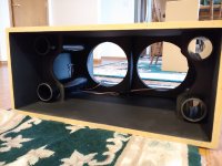
The enclosure is built as a series BP6 with following specs and pictures below:
- Rear chamber: 55-61L (depending on port configuration)
- Front chamber: 125-131L
- Internal ports comprise of four 46cm long PVC pipes which can be capped off to modulate internal port area (~0/45/90/135/190 square centimeters of port)
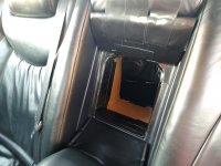
- Front port is 27cm long, with 489 square centimeters of area. In front of this there is another ~10cm of effective length having an area of ~900 square centimeters where the arm-rest recesses.


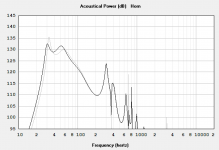
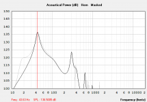
Enclosure has been modeled in Hornresp taking into account all port configurations and corresponding displacements @ 1kW RMS. Overall, the response of the box with the cabin gain is close to expected as we see in the RTAs that follow.
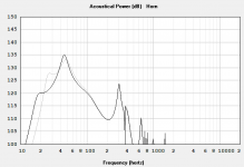
Below are Hornresp graphs which show the five different configurations:
4 ports open vs. 3 ports open
2 ports open vs. 1 port open
1 port open vs. 0 ports open (4th order mode)


I've taking many measurements with UMIK-1 at relatively low volume (well within any limits of microphone clipping). I'm noticing an intricacy in 4th order mode as well as 1 and 2-port 6th order modes that deviates from the sims in regards to peak output. Based on modelling I'd expect it to peak harder than the next closest configurations (1-2 ports open) by ~2-4dB respectively but that does not appear to be the case. At much higher power (1000W+) I've also RTAd the vehicle with the mic outside the window (in order not clip the mic inside the vehicle) and the same discrepancy is observed.
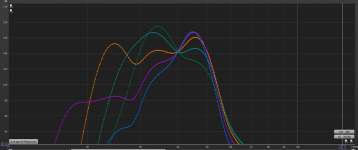
First set of measurements are with front windows open with UMIK at headrest (probably less than <5W). Box configurations can be identified by their low-freq shelf.
Green: 4 ports
Light green: 3 ports
Orange: 2 ports
Purple: 1 port
Blue: 0 ports (4th order)

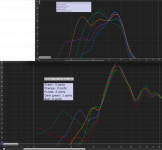
Second set of measurements are with all windows open with UMIK outside of car, ~1m away from B-pillar at same power. It's clear the car has optimal resonance mode at ~46-47Hz which is the the rough range where I'd like to target for peak SPL. The trace colors are different in this chart.
Green: 4 ports
Orange: 3 ports
Purple: 2 ports
Dark green: 1 ports
Red: 0 ports

For anybody wondering on why I want it to peak harder, it's to optimize this enclosure in these port configurations for SPL competition. I like having the modularity to switch port configurations on the fly for when I daily drive and when I want to compete. For reference before I got the UMIK, for competition I set it up as a 4th order and on the first go it did a 146.1 @ 42Hz on a Termlab at around 1kW of power. Now with the UMIK, I now have more insight into what's going on and I'm wondering if 4th order may not be optimal regard to SPL.
Was hoping to get some insight as to why this might be happening.
In terms of some factors:
- I don't believe that it's port compression as this relative behavior happens at low volumes. Furthermore, even at ~2kW there is no audible noise from the port.
- Could it be impedance being drastically difference in 4th?
- As this is done at low power I doubt I am seeing large-signal driver effects relating to BL-change vs. excursion as the drivers are barely moving when taking these measurements.
- For sealing up the ports, I am using slip-on 3" PVC test caps (very elastic). They don't leak but I do know that they are thin enough to resonate but I'm doubting this is significant.
- Could there any issues with the bracing/port supports/ports causing some tuning effect inside the box (only thing I've considered is just their displacement)?
I'm just in the process of updating the next iteration of my enclosure in my LS430 and noticing some modelling/real world discrepancies which I'd like to get some opinions on.
First for equipment, the system is comprised of:
- Two 12" DC Audio XLs (3" 8-layer flatwound DVC option, 2200W RMS a piece, QTS = ~0.38)
- Rockford Fosgate T1500.1BDCP (regulated at 1900W/1800W/1200W at 1/2/4 ohms respectively)
- Final impedance is wired to 1-ohm
- ~200L 4th/6th order adjustable enclosure
The enclosure is built as a series BP6 with following specs and pictures below:
- Rear chamber: 55-61L (depending on port configuration)
- Front chamber: 125-131L
- Internal ports comprise of four 46cm long PVC pipes which can be capped off to modulate internal port area (~0/45/90/135/190 square centimeters of port)
- Front port is 27cm long, with 489 square centimeters of area. In front of this there is another ~10cm of effective length having an area of ~900 square centimeters where the arm-rest recesses.
Enclosure has been modeled in Hornresp taking into account all port configurations and corresponding displacements @ 1kW RMS. Overall, the response of the box with the cabin gain is close to expected as we see in the RTAs that follow.
Below are Hornresp graphs which show the five different configurations:
4 ports open vs. 3 ports open
2 ports open vs. 1 port open
1 port open vs. 0 ports open (4th order mode)
I've taking many measurements with UMIK-1 at relatively low volume (well within any limits of microphone clipping). I'm noticing an intricacy in 4th order mode as well as 1 and 2-port 6th order modes that deviates from the sims in regards to peak output. Based on modelling I'd expect it to peak harder than the next closest configurations (1-2 ports open) by ~2-4dB respectively but that does not appear to be the case. At much higher power (1000W+) I've also RTAd the vehicle with the mic outside the window (in order not clip the mic inside the vehicle) and the same discrepancy is observed.
First set of measurements are with front windows open with UMIK at headrest (probably less than <5W). Box configurations can be identified by their low-freq shelf.
Green: 4 ports
Light green: 3 ports
Orange: 2 ports
Purple: 1 port
Blue: 0 ports (4th order)
Second set of measurements are with all windows open with UMIK outside of car, ~1m away from B-pillar at same power. It's clear the car has optimal resonance mode at ~46-47Hz which is the the rough range where I'd like to target for peak SPL. The trace colors are different in this chart.
Green: 4 ports
Orange: 3 ports
Purple: 2 ports
Dark green: 1 ports
Red: 0 ports
For anybody wondering on why I want it to peak harder, it's to optimize this enclosure in these port configurations for SPL competition. I like having the modularity to switch port configurations on the fly for when I daily drive and when I want to compete. For reference before I got the UMIK, for competition I set it up as a 4th order and on the first go it did a 146.1 @ 42Hz on a Termlab at around 1kW of power. Now with the UMIK, I now have more insight into what's going on and I'm wondering if 4th order may not be optimal regard to SPL.
Was hoping to get some insight as to why this might be happening.
In terms of some factors:
- I don't believe that it's port compression as this relative behavior happens at low volumes. Furthermore, even at ~2kW there is no audible noise from the port.
- Could it be impedance being drastically difference in 4th?
- As this is done at low power I doubt I am seeing large-signal driver effects relating to BL-change vs. excursion as the drivers are barely moving when taking these measurements.
- For sealing up the ports, I am using slip-on 3" PVC test caps (very elastic). They don't leak but I do know that they are thin enough to resonate but I'm doubting this is significant.
- Could there any issues with the bracing/port supports/ports causing some tuning effect inside the box (only thing I've considered is just their displacement)?
Attachments

Last edited:
Recon440,I'm just in the process of updating the next iteration of my enclosure in my LS430 and noticing some modelling/real world discrepancies which I'd like to get some opinions on.
1) I've taking many measurements with UMIK-1 at relatively low volume (well within any limits of microphone clipping). I'm noticing an intricacy in 4th order mode as well as 1 and 2-port 6th order modes that deviates from the sims in regards to peak output. Based on modelling I'd expect it to peak harder than the next closest configurations (1-2 ports open) by ~2-4dB respectively but that does not appear to be the case.
2)First set of measurements are with front windows open with UMIK at headrest (probably less than <5W).
Second set of measurements are with all windows open with UMIK outside of car, ~1m away from B-pillar at same power. It's clear the car has optimal resonance mode at ~46-47Hz which is the the rough range where I'd like to target for peak SPL.
3)For anybody wondering on why I want it to peak harder, it's to optimize this enclosure in these port configurations for SPL competition.
4)I like having the modularity to switch port configurations on the fly for when I daily drive and when I want to compete. For reference before I got the UMIK, for competition I set it up as a 4th order and on the first go it did a 146.1 @ 42Hz on a Termlab at around 1kW of power. Now with the UMIK, I now have more insight into what's going on and I'm wondering if 4th order may not be optimal regard to SPL.
5) I don't believe that it's port compression as this relative behavior happens at low volumes. Furthermore, even at ~2kW there is no audible noise from the port.
6) Could it be impedance being drastically difference in 4th?
7) For sealing up the ports, I am using slip-on 3" PVC test caps (very elastic). They don't leak but I do know that they are thin enough to resonate but I'm doubting this is significant.
8) Could there any issues with the bracing/port supports/ports causing some tuning effect inside the box (only thing I've considered is just their displacement)?
1) Measurement inside a lossy box car cabin will be subject to the cabin room modes and box losses, so both placement and transmission losses will cause deviations from the sim.
2)Opening windows changes the box (cabin) from sealed to ported, adding another order of complexity as well as changing the box (room) modal response. Outside the open window(s), you are measuring the port response of the box- which will change its tuning depending on the ratio of port area to box. All four windows open will have a higher Fb (~46-47Hz) than if only one or two windows were open.
3) You should work on optimizing response at the approved sensor (mic) placement for the division you compete in. Opening of windows will change the response at that location. Sitting in the seat opposite the mic will change response too.
4) Without knowing the competition rules, can't give insight as to the optimal solution for SPL.
5)At 146dB+, probably impossible to "hear" port noise, though port compression could account for several (measurable) dB of loss. If you are wearing good hearing protection, port noise would attenuated by 30 dB, while the low frequency is hardly attenuated at all.
6) Impedance will change considerably with voice coil heating, and the impedance peaks and dips change with the tuning, which changes with port compression.
7) Probably not too significant in the pass band you seem to be attempting to maximize, but they may be acting as tuned "bass traps", reducing a range of frequencies- note the reversal of output measured outside the car at 45 Hz vs 75 Hz with more ports covered with rubber ends.
8)Not likely.
Have fun, protect your hearing.
Art
Attachments
Hi Art,
Thanks for your insight!
There was one additional item I thought of that could be causing a deviation which is that the test caps are not placed on both sides of the ports but rather on front chamber (as this is quick and convenient to reach through the ski-pass and put them on):
- With capping the front, the volume of the pipes will be added to the volume of the rear chamber (~+4L for four ports).
- But... I believe it's more complex than just air pressurizing a simple sealed rear chamber as the pipes could be creating some additional effect. Aside from the rear space, the air is pressurizing the long tubular cavities which probably create some interesting turbulent effects. I'm guessing it would be akin to allowing the subwoofers "feel" a larger enclosure than the "physical" volume of the rear chamber + pipes would suggest, thus lowering the Q of the box...(akin to what stuffing a sealed box with polyfill does).
- I think this could be an explanation for lower and lower marginal gains of the 43-45Hz peak as you traverse from 4-3-2-1-0 ports... with each additional port plugged causing a lower and lower Q.
- I may run to Homedepot and grab 4 more test caps to plug both ends of the ports up to test this theory. Definitely doable for the 4th, but for all port configurations sub-optimal as it's a nuisance to open up the back of the box each time to put a cap on the rear. I like to take all measurements in a short time-frame to ensure repeatability instead of doing it over a period of days to exhaustively test all port configurations in such a fashion.
I'm realizing that with audio (especially car-focused), modelling gets you into the ballpark when you consider everything small-signal/anechoically but in practice there will obviously be deviations... the cabin, it's transfer function as well as how the it enclosure and that's not even mentioning how speaker parameter shift at 1000W+.
The biggest enjoyment I get from car audio is the process of making iterative adjustments and seeing the results. I can't believe I held off from buying an UMIK for so long as it really gives me more insight into quantifying such changes. This is actually the first time I've actually metered the vehicle as I was curious how competitive it would be and I've learned quite a lot into the different metering classes and what people do to optimize their scores.
For competition context, I tried out the new "Freestyle" dBDrag class where an 8" globe that houses the Termlab can be placed anywhere in the cabin ahead of the B-pillar, and you are free to close or open your doors during the run. The 146.1dB was put up with mic in the front passenger kick with just the driver's door open... I'm using this as a reference to compare to the UMIK at much lower volumes for testing.
Since then, I've taken many measurements (at low power as that's what the UMIK allows me to do, say ~115dB) and I was able to muster up an addition ~2.5dB from this baseline by opening windows, sliding the passenger seat forward, opening glove box, etc... you're not kidding when say that there are peaks and nulls in various places in the vehicle. For a typical reference measurement (sealed cabin, windshield) the vehicle put up a score of 142dB it's clear there are some improvements that can be made.
-Adam
Last edited: