I have seen once real measurements of 300B WE and Cetron 300B , only alternative in France in 80's . The deference is every little, only at low currents , but when comes to sound the tonality of the CETRON is brighter as if bass control is set at 9 o'clock .I would definitely compare resulting anode curves. 🙂
I have seen once real measurements of 300B WE and Cetron 300B , only alternative in France in 80's . The deference is every little, only at low currents , but when comes to sound the tonality of the CETRON is brighter as if bass control is set at 9 o'clock .
Then, one of tubes in the amp caused distortions closer to distortions of our perception, so they were better filtered out. I am getting similar effect using pentodes and beam tetrodes with external plain linear resistive feedback loops.
Wavebourn,
When you said: "with external plain linear resistive feedback loops" did you mean feedback loops that did not include:
The Output Transformer?
Capacitors that are in parallel with the feedback resistor?
Thanks.
When you said: "with external plain linear resistive feedback loops" did you mean feedback loops that did not include:
The Output Transformer?
Capacitors that are in parallel with the feedback resistor?
Thanks.
Wavebourn,
When you said: "with external plain linear resistive feedback loops" did you mean feedback loops that did not include:
The Output Transformer?
Capacitors that are in parallel with the feedback resistor?
Both. You can shape the transfer function playing with the ratio between nested feedback loops.
Wavebourn,
If I understood you correctly, all of the (nested) feedback loops, no matter how close (local), or even to almost global (but not quite global):
1. Do Not include the primary to secondary of the OTP.
2. Do Not have a capacitor across any negative feedback resistor.
Thanks.
If I understood you correctly, all of the (nested) feedback loops, no matter how close (local), or even to almost global (but not quite global):
1. Do Not include the primary to secondary of the OTP.
2. Do Not have a capacitor across any negative feedback resistor.
Thanks.
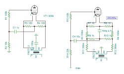
I understood why CETRON has bright sound when I replaced the 300B Shugwang with 2A3C of same brand . By applying an external 2.5V ac using the center tap grounded, I got far better mid and highs but where the bass did evaporate ? By reducing 5v to 2.5v using a pair of 0.5 ohm , I lost all the goodness of the highs but the bass reappeared ,loose , boomy . So I adjusted for best bass and added with high pass 70hz the highs . The spectrum of the got dramatically enlarged comparing to 300B . There I understood why WE used bootstrap , and why CETRON had bright sound .
My circuit uses two separate power supplies for the output and the driver to have directly linked .

My circuit uses two separate power supplies for the output and the driver to have directly linked .
Attachments
Last edited:
Wavebourn,
If I understood you correctly, all of the (nested) feedback loops, no matter how close (local), or even to almost global (but not quite global):
1. Do Not include the primary to secondary of the OTP.
2. Do Not have a capacitor across any negative feedback resistor.
No, I did not mean that. Capacitors have nothing to do with that, and of course you can use one of loops across an output transformer. I did not mean frequency dependence curve, I meant dependence of distortions on the signal level. If it resembles our own perception's distortion profile, it gets ignored. If does not, it is audible, even if distortions are much lower, but differently depend on loudness.
The point being that replacing measurement with auditory assessment you could run into a situation that would allow for distortion to enjoy. That's considered bad engineering, as is overall feedback as a "cure all" recipe for a good amplifier. It's considered good engineering to investigate where the distortion originates and improve the circuit.
Wavebourn,
I guessed that you did not mean the frequency response curve.
But a transformer does have distortion that changes at high levels, and the relative strength of harmonics can change at that time. And that can be different for single ended than for push pull.
What I was more interested in was the relative strengths of the harmonics.
I guessed you meant that.
But now I think you are also saying that the relative strengths of the harmonics need to:
1. Either not change as the amplitude changes,
2. Or change at the same rate as the ear changes its relative strength of harmonics,
3. Or change at the same rate as a musical instrument changes its relative strengths of harmonics.
"Natural" sounding amp?
As a generalization, an amplifier that has no distortion in earlier stages, and only the output stages will have dominant 2nd harmonic for an SE output, and dominant 3rd harmonic for a push pull stage.
For a well behaved SE stage, increasing the drive by 10 dB will increase the harmonics
this way:
Starting with drive, c, at 0 dB
Then Drive, c, increase by + 10 dB
2nd + 20 dB (+ 10 dB relative to the 0 dB drive level)
3rd +30 dB (+20 dB relative to the 0 dB drive level)
I used to describe that as 3 race cars.
1st Car (fundamental) started first, speed 100 MPH
2nd Car started second, speed 200 MPH
3rd Car started last, speed 300 MPH
Eventually the 2nd car caught up to the 1st at a 100 MPH closure rate
Eventually the 3rd car caught up to the 1st at a 200 MPH closure rate
Of course in an amplifier for its usable dynamic range, the distortion never catches up to the fundamental. That is where the car analogy falls apart.
But watching the harmonic structure on an FFT shows that the higher the order of the distortion, the faster it changes relative to the fundamental
But that also means that the higher order distortions do not even appear, until the drive level is so large that the 2nd and 3rd are already very strong.
Last edited:
- Home
- Amplifiers
- Tubes / Valves
- Why doesn’t a 2a3 equal two 45s sonically?