Seems to me that screen grid absorption of reduced cathode current is more likely. With low plate voltage, the electrons are more easily diverted to the constant screen grid voltage. Explaining why low screen V fixes the problem. Mis-aligned grids could also cause/agravate that, or de-focusing of the grid 1 shielding/focusing by increased negative grid 1 voltage beyond optimum.
Assuming you are addressing my question and you mean direct electrons from the cathode, not secondaries from the anode, that's just a different way of saying the ratio of direct screen current (ie not that due to secondary emission) to anode current changes with different anode currents as control bias is changed.
Why would it, as since the anode voltage and screen voltage has not changed, the electric field gradient in the vicinity of the screen has not changed?
The gradient will change nearer the control grid of course, but with a typical control grid range of say 0 to - 5 volt or so (as with 6BH6 - a sharp cutoff tube), the change is just about negligible compared to the typical 100 to 150 volts on the screen.
If you are correct, it means that remote cutoff tubes (or tubes with a long grid base) should show broader or greater kinking. Do they?
Last edited:
I thought "work function" referred to the thermal EMF developed across dissimilar metal joints.
There is work function and there is work function (energy required to get electrons to leave a conductor). Work function involved with different metals in vicinity of each other; work function determining photo emission, work function determining thermionic emission, etc etc. All these work functions are in solid state physics theory the same work function, but ......
The problem with work function is that there are different ways to measure it, and the different ways don't agree well. And most are not accurate - eg measuring the work function by plotting emission versus temperature involves subtracting a large number from another to get a small difference - hence a large subtraction error.
And work function is itself temperature dependent, its not just the temperature dependence due to the temperature term in the emission equation.
All about work function you didn't want to know....
Yes, direct cathode emission.
With reduced plate voltage, the electrons are more likely to get deflected sideways towards a screen grid wire when in near proximity.
With Crazy Drive, the screen V drops as the cathode/plate current drops.
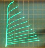
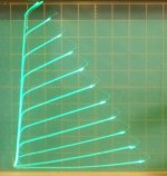
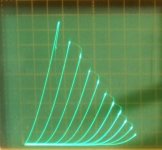
Below, curves for a 26LX6 TV Sweep with conventional grid 1 drive (fixed grid 2 V) and 26LX6 with Crazy Drive (grid 2 V, and grid 1 V proportional to plate current). Notice how the kinks have vanished.
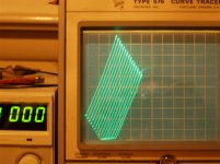
Using the Crazy Drive configuration for N Fdbk instead, becoming "Crazy Fdbk" and cathode Voltage drive (not current drive as in cascodes), one can get straight parallel plate "curves".
No kinks, and no diode curves, just straight parallel lines. A wire with gain. Figure 3 below. (camera was hand held, a little shaking apparent)
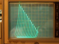
Just to be complete, figure 4 shows a $1 21HB5A TV Sweep using a conventional plate to grid 1 shunt Schade like N Fdbk with cathode Voltage drive. Notice the triode curves are a near copy of 211 triode curves, just a higher current scale and lower plate V scale here. Figure 5 is the 21HB5A in conventional triode wired configuration. Notice the roll-over in the curves producing 2nd harmonic.
-----------------------------
On the hysteresis thing: I was using a TEK 576 curve tracer (modified for tube grid voltages). The 576 provides the option for all traces to be using the same slope of the 60Hz power or it can use alternating slopes of power line for alternating plate sweeps. One can see consistency between alternate plate traces that way, but differences with the other alternate trace set. No fuzziness in the traces, just solid lines that are alternatingly consistent, but inconsistent with the alternate set. So HF oscillation seems unlikely. I also have grid stopper resistors and strings of ferrite beads on the plate wire. N. Crowhurst once talked of tube hysteresis, I've solved it (at least for some tubes) The 6JK6 used in a famous receiver has terrible hysteresis without the fix.
With reduced plate voltage, the electrons are more likely to get deflected sideways towards a screen grid wire when in near proximity.
With Crazy Drive, the screen V drops as the cathode/plate current drops.
Below, curves for a 26LX6 TV Sweep with conventional grid 1 drive (fixed grid 2 V) and 26LX6 with Crazy Drive (grid 2 V, and grid 1 V proportional to plate current). Notice how the kinks have vanished.
Using the Crazy Drive configuration for N Fdbk instead, becoming "Crazy Fdbk" and cathode Voltage drive (not current drive as in cascodes), one can get straight parallel plate "curves".
No kinks, and no diode curves, just straight parallel lines. A wire with gain. Figure 3 below. (camera was hand held, a little shaking apparent)
Just to be complete, figure 4 shows a $1 21HB5A TV Sweep using a conventional plate to grid 1 shunt Schade like N Fdbk with cathode Voltage drive. Notice the triode curves are a near copy of 211 triode curves, just a higher current scale and lower plate V scale here. Figure 5 is the 21HB5A in conventional triode wired configuration. Notice the roll-over in the curves producing 2nd harmonic.
-----------------------------
On the hysteresis thing: I was using a TEK 576 curve tracer (modified for tube grid voltages). The 576 provides the option for all traces to be using the same slope of the 60Hz power or it can use alternating slopes of power line for alternating plate sweeps. One can see consistency between alternate plate traces that way, but differences with the other alternate trace set. No fuzziness in the traces, just solid lines that are alternatingly consistent, but inconsistent with the alternate set. So HF oscillation seems unlikely. I also have grid stopper resistors and strings of ferrite beads on the plate wire. N. Crowhurst once talked of tube hysteresis, I've solved it (at least for some tubes) The 6JK6 used in a famous receiver has terrible hysteresis without the fix.
Attachments
Last edited:
Smoking Amp:-
You may have fallen into a basic trap. Tube parasitic oscillation can be well up in the VHF region, well beyond the video bandwidth of the Tek 576. So you won't see the oscillation as "fir" on the traces.
Even engineers who should have known better have had their products knocked back by the FCC and its equivalents in other countries, because their design was oscillating and radiating like crazy at VHF or UHF and they just didn't know because they only used a low bandwidth (10 or 15 MHz) CRO. One of the reasons why cathode followers sometimes mysteriously cause distortion for beginners.
The reason why the 576 has 2 sweep modes which can show you hysteresis is because it was primarily designed to curve trace semiconductors in which thermal effects make hysteresis important. And you can use it to check certain passive components in which hysteresis is a fault mode. What Tek called "looping" can look like hysteresis too.
When testing or using tubes, you often need stoppers on the screen as well as the anode. Generally you don't need them on the suppressor due to internal capacitance and the suppressor's low gm.
Your fig 1 shows kinking increasing as anode current is reduced, and then kinking reducing somewhat as the current is reduced further. I've seen that in some tubes too.
Some types do that in quite a pronounced way, and that does have me mystified.
Last edited:
I see your point about the actual plate and screen potentials staying the same (for this case). The variation in kinking here is related to either current change or grid 1 Volts change obviously. But the presence of beam current density itself changes the potential profile by just the presence of the distributed space charge. Not saying that is the cause, but could be related.
The grid 1 voltage would affect the micro beam focusing between the grid 2 wires. There should be an optimum grid 1 voltage for minimal grid 2 current, with screen current increases to either side of that optimum grid 1 voltage (over focusing or under focusing).
-----------------------------------
On the hysteresis, with 15 traces of alternating plate V sweep direction on the TEK 576, I see two different knee curves overlapped for each plate curve. (due to the odd number of traces causing alternating sweep direction for each curve set scan ) With 14 traces I see the pattern frozen, with alternate plate curves having the two versions of knee.
For 6JC6 (Japan version) and for 6JK6 tubes, I can cure the "hysteresis" by putting a small positive voltage on grid 3 (beam plates). I don't see how that could be VHF oscillation. I guess I could put the 7904 scope on it to see if any VHF is there. But I don't see how it could produce such coherent results on the 576. (well, as you say, rectification in the vertical channel could do that I guess, but then that would just be hysteretic VHF bursts, still a problem)
I don't see the problem occur with 12HL7, 12GN7, 9KC6 or 12HG7, all higher gm tubes. I think I did see this issue occur with one 7788 tube, but not with some others.
Smoking Amp: "over focusing or over focussing"
Now I see what you are getting at. I need to dig out some potential gradient plots ("rubber sheet" plots) to see if it is plausible.
Looping, as Tek calls it, caused by bandwidth limitations in the current sensing and scan circuits of the tracer, can look like hysteresis.
I find it really hard to accept that a vacuum tube can show hysteresis in characteristics. One thing I learnt long ago is that if a tube shows apparent hysteresis, it is oscillating so high in frequency your instruments cannot see the oscillation. Either that or it is a thermal effect of a faulty tube (grid wires sagging with heat) - this being a very rare problem.
The nature of VHF or UHF parasitic oscillation is that it comes and goes with quite minor changes in the circuit or tube voltages. One old timer's dodge is to put one's finger or just a bit of insulated wire on or near an electrode. If the curves change, its because you stopped or started VHF or UHF oscillation by adding a bit of lossy reactance.
A small voltage of either polarity (depending on the quirks of a particular tube and test environment) on the suppressor is entirely plausible for stopping or changing parasitic oscillation, as it would change both anode and screen gm.
What possible reason can there be for a tube to show hysteresis? What you are saying is that the tube has somehow remembered what you did to it for 15 or 16 sweeps i.e. about 250 millisec. How can it do that?
All of us in this game have seen amplifiers that when fed with a sinewave, oscillate for a short period during part of each cycle, as the input cycles a tube (or transistor) through its variation in gm that just happens to favour oscillation at whatever frequency stray capacitance, transit time, and inductance favours. And occasionally an amplifier that works fine of sinewaves but goes into a flap with a triangle wave input. And, naturally, sounds dreadful on music.
Your biasing the suppressor grid isn't any different.
A tube with a higher gm is more likely to oscillate, all other things being equal. But they aren't equal. Generally, power tubes have higher gm than eg small frame grid RF tubes, due to greater cathode area. But they also have greater electrode spacing, which means transit time is longer, which may in a given circuit reduce the chance of oscillation.
Well, I'll find a tube with the "hysteresis" problem and put a HF scope on it.
I know I have seen a tube textbook here with a diagram and explanation of how the space charge is unstable in some (design) conditions near the knee to the dynamic direction of entry (plate voltage). Some kind of dynamics is different with the space charge cloud present (I think just beyond grid 2) versus no space charge formed yet. Grid 3 voltage would seem likely to affect the space charge next to it. A quick look through the most likely texts here and I don't see any entry for "hysteresis". Maybe it didn't rate an index entry or they called it something else. I'll look through the "Pentode" derivation sections next. I know N. Crowhurst once mentioned tube hysteresis, but I don't think he gave an explanation. I think it involved beam pentode designs with sharp knees.
I know I have seen a tube textbook here with a diagram and explanation of how the space charge is unstable in some (design) conditions near the knee to the dynamic direction of entry (plate voltage). Some kind of dynamics is different with the space charge cloud present (I think just beyond grid 2) versus no space charge formed yet. Grid 3 voltage would seem likely to affect the space charge next to it. A quick look through the most likely texts here and I don't see any entry for "hysteresis". Maybe it didn't rate an index entry or they called it something else. I'll look through the "Pentode" derivation sections next. I know N. Crowhurst once mentioned tube hysteresis, but I don't think he gave an explanation. I think it involved beam pentode designs with sharp knees.
Last edited:
Daring to disagree with heavyweights here....
But... in your last example Keit, power tube, high gm, high electrode spacing...
What makes you certain that transit time being longer, would reduce the chance of oscillation?
From my noob POV, increased transit time, is the same as saying increased phase displacement/akin to logic latency - in my mind this would mean the opposite, a larger propensity for those type of tubes to oscillate.
Last edited:
Yours: "Some kind of dynamics is different with the space charge cloud present (I think just beyond grid 2) versus no space charge formed yet."
Well, yes, obviously. But the electron velocity is such that it takes nanoseconds to establish any steady state space charge. After all, it takes only nanoseconds for the slowest of electrons to get from cathode to anode. So your theory here doesn't stand up. So you might see a sort of hysteresis (it still isn't really hysteresis) at VHF or or UHF frequencies, but NOT at the sweep rate of a curve tracer. Especially on your Tek tracer that uses 60Hz sine or rectified sine waves as the sweep.
I've never heard of hysteresis in tube behaviour, except as I said, the false hysteresis effect of parasitic oscillation, which is well known to us who have been in the game professionally since the tube days.
If you could remember and cite the Crowhurst reference, that would be helpful.
Daring to disagree with heavyweights here....
But... in your last example Keit, power tube, high gm, high electrode spacing...
What makes you certain that transit time being longer, would reduce the chance of oscillation?
From my noob POV, increased transit time, is the same as saying increased phase displacement/akin to logic latency - in my mind this would mean the opposite, a larger propensity for those type of tubes to oscillate.
I might have not written as clearly as I should. What I meant was that when gm is high enough to allow stray reactances to set up oscillation, the transit time MAY introduce additional phase shift so that oscillation at that frequency will not occur. Or, depending on the circuit, it MAY promote oscillation. As you know, for oscillation, there is an optimal phase shift (in phase as we say), its not a case that more is better.
A case of sometimes it does ... and sometimes it doesn't .... I was giving an example of how it can come about that a certain tube may oscillate, but a higher gm tube in the same environment MIGHT not. It equally may well oscillate. Perhaps a little more likely it will, but it might not.
Also, the effect of transit time is not merely a phase shift. It also causes a reduction of gain at frequencies where it is significant. And also adds reactive loading, as the grid signal causes bunching of electrons at these frequencies, and as these bunches of electrons travel through the tube, they cause by repulsion electrons to scuttle in and out of each grid. This means the tube may (or may not - that's the nature of the parasitic beast) want to oscillate at a frequency at which the environment causes too much loss.
If it were otherwise, it wouldn't have taken until the 1940's for the experts to develop good UHF tubes.
Last edited:
I've found a section 10.6 in Spangenberg's book "Vacuum Tubes" that treats beam power tube dynamics. Pages 259 thru 265. Diagram 10.15 shows an idealized hysteretic knee.
Pages 291 thru 297 mention some focusing effects of a suppressor grid that can cause a 2nd space charge to accumulate in front of the plate, causing further suppression of secondary emission. Might have some relevance to the kink issue.
Pete Millett has the book available scanned on his site if you don't have it available.
Technical books online
Last edited:
Smoking-amp, Thanks. I already have Spangenberg in my collection, but not immediately at hand (there's not enough room in my house for all my electronic stuff - got some in the roof space). I will consult it later today and maybe post again to this thread.
Smoking-amp:-
You are correct in that Spangenberg (1948) describes in his Sect 10.6 a hysteresis effect in beam power tubes. He describes how this is due to a sort of internal positive feedback effect on the post screen space charge, working much like the action of a schmitt trigger circuit.
So I was quite wrong in denying hysteresis in tubes.
But note that this snap action at and below the anode curve knee looks quite different to the apparent hysteresis above the knee shown in your fig 1 in your earlier post. Also, Spangenberg's snap-back hysteresis mode is only applicable to beam power tetrodes and possibly to beam pentodes, but not applicable to pentodes like the 6JC6 that aren't "kinky".
So, I still think you are most probably mistaking parasitic oscillation effects for actual tube hysteresis.
The snap-back phenomena described by Spangenberg would, of course, be an effective cause of very high frequency oscillation (as Spangenberg points out in stating that it can be used to make an oscillator), which may well upset limited bandwidth instrumentation like curve tracers and tube testers, but only below the knee (region c'-g-g' in Spangenberg's Fig 10.15).
Regarding focusing effects making the kinking come and go at different anode currents - yes you definitely have something there. It should be possible to nail it down by measuring the ratio of screen current to anode current for sets of fixed anode and screen voltages, changing control grid bias so as to get different currents for each plot. This I intend to do, but at this time I don't have enough meters and accurate variable power supplies to set it up.
Many thanks for your help in talking this through.
Keit
Smoking-amp:-
Note that the hysteresis described by Spangenberg will not cause audible distortion in beam power output stages beyond what you would get by overdriving the tube anyway. But the apparent hysteresis depicted in your fig 1 WOULD cause distortion.
Another reason why I think it's an artifact of testing and not a "real" effect.
- Home
- Amplifiers
- Tubes / Valves
- Why does secondary emission show at low current?