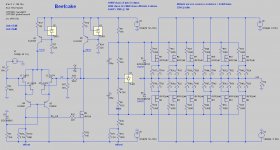
In an attempt to better model the distortion of a design I'm working on I added ripple to my power rails in SPICE. I have separate rails for the IPS/VAS (shunt regulated) and OS (CRC filtered).
To my surprise I found that the THD goes down with a bit of ripple on the output stage PSU rails. The trough is at 0.9V, with 1.2V having risen back to what it is at 0V.
Is this real, or just an anomaly in SPICE?
(FWIW, any increase in IPS/VAS PSU ripple has the expected effect: an increase in THD.)
Attachments
Interesting! .... I would try varying the phase and/or frequency of the ripple with respect to the signal. There may be some "fortunate" intermodulation going on, as the ripple frequency of 100 Hz divides the 1 kHz signal frequency.
If that doesn't give some insight I'd try varying the (dc) ops power supply voltages, maybe there is some sensitivity to supply voltage (???)
If that doesn't give some insight I'd try varying the (dc) ops power supply voltages, maybe there is some sensitivity to supply voltage (???)
The ripple shouldn't affect the output transistors unless the amp is driving really hard and the output signal gets close to the rails.
Ripple definitely affects the front end so I usually RC the supply on the front end.
Ripple definitely affects the front end so I usually RC the supply on the front end.
Is the lower distortion some manifestation of dithering happening at crossover?
Is the distortion really down or moving to a different frequency?
Is the distortion really down or moving to a different frequency?
I was measuring the distortion at 1W, so it's not near the rails and it's running class A up to 100W so there's no crossover distortion.
I'll try varying the frequency...
I'll try varying the frequency...
Yep, THD goes up when I change the ripple to 411Hz or the input/FFT to 1.33kHz.
Kind of suggests those of us in 50Hz countries ought to be using something other than 1kHz for their FFTs?
Kind of suggests those of us in 50Hz countries ought to be using something other than 1kHz for their FFTs?
OK, so with a 1.33kHz input and a ripple skewed to 113hZ, I get the following for the OS:
My conclusion is that 300mV -> 100mV is worth pursuing; the others not so much?
Code:
ripple    THD    improvement
------  -------  -----------
 300mV  0.00121
 100mV  0.00112      8%
  10mV  0.00108      4%
   1mV  0.00107     <1%
My conclusion is that 300mV -> 100mV is worth pursuing; the others not so much?
I was thinking the 8% improvement was the operative number. Add a few such improvements up and the difference between, say, 1% and 0.6% at full output might be noticeable.
But I looked into that and the sym reaches 1% THD only due to the onset of clipping. Just prior to that THD is only 0.06%. Even a full 1V of ripple barely gets that to 0.07%....
But I looked into that and the sym reaches 1% THD only due to the onset of clipping. Just prior to that THD is only 0.06%. Even a full 1V of ripple barely gets that to 0.07%....
Hi Jeff,
If you try to measure at the frequency that is not a multiplication of 100 (your ripple frequency), say, at 987 Hz - will you see the same effect?
Cheers,
Valery
If you try to measure at the frequency that is not a multiplication of 100 (your ripple frequency), say, at 987 Hz - will you see the same effect?
Cheers,
Valery
@Valery, see post #6. The short answer is no, it behaves as one would expect (although I used 1.33kHz).
@Valery, see post #6. The short answer is no, it behaves as one would expect (although I used 1.33kHz).
Ah - sorry, missed that post 🙂
Then I think what's happening - in simulation, as soon as the input frequency is the multiplication of the ripple frequency (all the sources are synchronized in phase by the simulator), the input capacitance of HexFETs (rather high and non-linear depending on Vgd) gets slightly "bootstrapped" by the rails ripple at some points in time, resulting in small distortion decrease.
In fact, using the rails, bootstrapped by the output signal, you can make the output HexFETs working at almost constant Vgd, taking out the most of their input capacitance, noticeably decreasing the distortion.
Expect a PM.
you may be seeing a balance of N - P channel ( on resistance ) of the fets as there appears to be no negative feedback to correct the output stage. A tube stage would place noise on the output if it is present on either rail or the sometimes the heater.
I suspect your "THD" is (correctly) counting rail-junk as Distortion. Your ear will not hear it as Distortion but as "noise", buzz.
Convert your "percent THD" to actual Volts.
Assuming these numbers are for about 30V output, I get:
300mV ripple - 0.00121% - 0.36mV
You have 800:1 ripple rejection in your output stage. This seems quite likely for a MOSFET with NO overall NFB.
Ah, you tested at 1W. Then levels are 10X lower and you have 8,000:1 rail rejection. That may be true in SPICE. In real life the Drain curves may not be so flat, and stray parasitics matter.
0.36mV is 78dB below 1 Watt. For typical speakers the buzz will be 10dB SPL. That would be reasonable; but 300mV ripple at idle may not be reasonable. An economic design works for 5% ripple at full power. An AB BJT amp may idle at 1/100th of full roar current, so 0.05% ripple, which is 24mV so reasonable. However MOSFETs tend to need to be idled warmer, especially with zero NFB around them, so pencil 240mV ripple. It is a consideration.
@PRR, while my SPICE sim doesn't show it, I currently have a toggle switch to go between "local" (IPS + VAS) feedback and global (IPS + VAS + OS) feedback. Should prove interesting.
Anyway, thanks for the in-depth analysis. I'm slowly getting my head around this.
Speaking of which, my full-power bandwidth wasn't very good (56kHz). Going on the idea that gate capacitance might be killing my slew rate, I applied @vzaichenko's bootstrap theory and replaced my VAS's CCS with an output-bootstrapped one. My full-power bandwidth shot up to 96kHz! Is that real?
...my full-power bandwidth ...
You've got the sim. Put a current probe on M9, drive high amplitude high frequency. Is M9 going anywhere near zero current?
Very interesting! Remember that LTSPICE .four command just measures harmonics of one frequency. Any inter-modulation will be ~ignored unless the product lands on a harmonic. Implication is that we really need two-tone analysis in SPICE. I don't see anything in <help> about "two-tone" or "intermodulation", but it looks like it is handled in certain RF simulators.
@PRR, is that another way to measure FPBW? M9 runs out of current at about 115kHz.
Interestingly, I get the same 115kHz for all three versions now (bootstrap, 2-BJT CCS and BJT+TL431 CCS). And I can't provoke the "bad" 56kHz FPBW I was seeing earlier. Maybe I wasn't using a small-enough time-step, or a high-enough frequency earlier?
Interestingly, I get the same 115kHz for all three versions now (bootstrap, 2-BJT CCS and BJT+TL431 CCS). And I can't provoke the "bad" 56kHz FPBW I was seeing earlier. Maybe I wasn't using a small-enough time-step, or a high-enough frequency earlier?
In other news, I did discover that the BJT+TL431 CCS goes into oscillation at 2MHz. A 10u bypass on the TL431 cleans this up neatly, but at that point the parts count is higher than the 2-BJT version and I'm not sure it's buying me anything.
Note that .four help notes suggests that viewing the wave FFT is more useful than .four but I don't think it provides a THD value. Anyone know how to integrate and measure the non-fundamental amplitude?
- Status
- Not open for further replies.
- Home
- Amplifiers
- Solid State
- Why does output stage like a bit of ripple?