I’m approaching this question from a historical perspective.
I know a lot of these valves are not intended for audio use. So what is the intended purpose of having curves like this in datasheets?
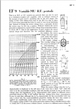
It’s shows the the screen current when triode strapped as a function of screen voltage. This must mean that designs would take current from the screen rather than the anode? What’s the consequences of that? Much lower currents!
I know a lot of these valves are not intended for audio use. So what is the intended purpose of having curves like this in datasheets?
It’s shows the the screen current when triode strapped as a function of screen voltage. This must mean that designs would take current from the screen rather than the anode? What’s the consequences of that? Much lower currents!
Attachments
Last edited by a moderator:
I think there is a 60k Ohm resistor tied in series from the Plate to the Screen.
That is not exactly what I would call Triode Strapped; just call it Highly Modified Triode Strapped.
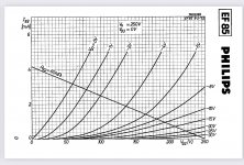
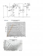
According to the graph:
Plate + 250V all the time
and G3 = 0V all the time.
Then, G1 voltage is varied from -30V to 0V.
The resultant G2 current is graphed (with the Screen Load line = 60k).
Hint: Change the 60k resistor to a 30k resistor, and the slope of the Screen Load Line will double upward, about 2x the current at any given screen voltage.
Notice that the screen current is cutoff at a G1 grid bias of approximately -35V or -40V.
Does that explain the graph?
That is not exactly what I would call Triode Strapped; just call it Highly Modified Triode Strapped.
According to the graph:
Plate + 250V all the time
and G3 = 0V all the time.
Then, G1 voltage is varied from -30V to 0V.
The resultant G2 current is graphed (with the Screen Load line = 60k).
Hint: Change the 60k resistor to a 30k resistor, and the slope of the Screen Load Line will double upward, about 2x the current at any given screen voltage.
Notice that the screen current is cutoff at a G1 grid bias of approximately -35V or -40V.
Does that explain the graph?
Last edited:
Not "rather than".
You apply positive voltage to any element inside a tube (plate, screen and even grid) and it will start attracting electrons from cathode, hence passing current.
Not all the same, to each its own, and that is shown in different graphs.
Say you have a triode strapped Pentode, applying , say, +300V to plate means screen will also get 300V (duh!!)
Each one will pull current.
Check the slopes of the family of G1 grid bias lines.
The slope of each G1 grid bias voltage line, is the Screen Resistance, rs, when G1 is at that voltage.
The screen resistance, rs, is something that some engineers want to know.
But, be careful, that is with the Plate fixed at 250V.
If the plate has 250V B+, and works into a real load, RL, and the plate voltage swing goes down to 50V, the screen current will go up sharply (and that effect is an other graph that you know, that shows a range of plate voltages, fixed screen voltage, a range of G1 bias voltages . . . all versus some very large screen currents).
Last edited:
(Would not let me edit my comment; updated here)
Thanks that’s really helpful, I understand the graph is basically using the screen as the anode and getting triode like curves.
So why does it appear in a data sheet? What’s the application of extracting from the screen to an engineer? There must be some advantages to using the valves in a circuit in this way? When I have seen triode strapped pentodes before the screen is strapped to the anode and suppressor to the cathode, and load lines are plotted with anode current against anode voltage with grid as the parameter.
boyfarrell,
I am sorry, my edits ended very close to your last post (you were probably still typing, so you did not see my final edits).
Re-read my Post # 5, and see if that answers your question.
Thanks!
I am sorry, my edits ended very close to your last post (you were probably still typing, so you did not see my final edits).
Re-read my Post # 5, and see if that answers your question.
Thanks!
Yes. Pentodes are facilitating! That’s all makes sense.
I should measure some of these tubes and report back… to eBay I go!
I should measure some of these tubes and report back… to eBay I go!
Not at all.I understand the graph is basically using the screen as the anode and getting triode like curves.
The Anode works as such *always*.
Tying screen to it changes curves, slope, maxium current,etc. so now tube *behaves* as a Triode but always the Anode is the main current drain.
BUT screen takes significant current too, dissipates power, etc. and Datasheet shows that.
But it never replaces the anode, by any means.
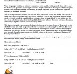
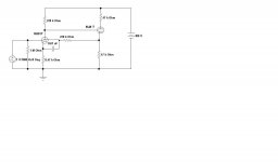
Screen Resistance Measurement
The information on that graph is very useful, in particular in the designing of a NFB amplifier. Here is one way of determining screen resistance of the screen in a pentode.
I'll add to this later, an example of the information as applied to a on a common FB amplifier..🙂
The information on that graph is very useful, in particular in the designing of a NFB amplifier. Here is one way of determining screen resistance of the screen in a pentode.
I'll add to this later, an example of the information as applied to a on a common FB amplifier..🙂
Attachments
Not at all.
The Anode works as such *always*.
Thanks, yes that clear, I’m aware of the current split between screen and anode. Please excuse my imprecise vocabulary.
Last edited by a moderator:
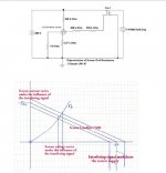
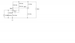
Estimation of Screen Resistance with an Example
This one is the front end of the Heathkit UA1 Amplifier. The screen resistance & its bypass cap forms part of the NFB stabiliztion.🙂
More to go as I dig it out. All these reports are on PDF but for some unknown reason folks on DIY don't take the time to open.😀
This one is the front end of the Heathkit UA1 Amplifier. The screen resistance & its bypass cap forms part of the NFB stabiliztion.🙂
More to go as I dig it out. All these reports are on PDF but for some unknown reason folks on DIY don't take the time to open.😀
Attachments
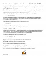
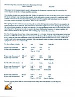
Step Size due to Screen Bypass
Here are bench tests to determine the change of gain due to the screen bypass. Something designers need to know when working on a NFB amplifier.
Here are bench tests to determine the change of gain due to the screen bypass. Something designers need to know when working on a NFB amplifier.
Attachments

Last edited:
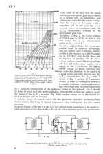
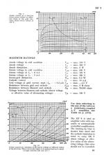
According to Philips the EF9 was their 1st Variable Mutual Conductance valve featuring "sliding screen grid voltage" operation as If / HF amplifier for improved gain control.
Requires a very high value unbypassed screen resistor.
Hence the respective curves in the data sheets.
The EF85 is one of the successors for this service with similar characteristics.
Philips_ElectronicValves_BookII_1949 has a detailled description for the EF9 on pg. 81-85.
Requires a very high value unbypassed screen resistor.
Hence the respective curves in the data sheets.
The EF85 is one of the successors for this service with similar characteristics.
Philips_ElectronicValves_BookII_1949 has a detailled description for the EF9 on pg. 81-85.
Attachments
Last edited:
> Variable Mutual Conductance valve featuring "sliding screen grid voltage"
Yes, that is THE reason to document that specific screen resistor. In fact that is one reason I got a copy of Philips 1949.
But that is NOT relevant on a Hi-Fi chat-group, and there may be NO good(*) reason to use this class of very-bent tube in good audio.
(*)It directly extends the "undistorted" dynamic range of a compressor. There's alreayd far too much compression in recordings, and IMHO if you need more you do it digitally.
Remote Cut Off Pentode, great for RF & IF Amplifiers. But in audio, a real good way to create even order harmonix. Stuff it into the FX Box.😱
The EF85 is one of the successors for this service with similar characteristics.
Philips_ElectronicValves_BookII_1949 has a detailled description for the EF9 on pg. 81-85.
This really helped, thanks so much, I didn’t know about this reference. I’m quite interested in the historical/technical evolution of the technology, and why certain designed were introduced, what problems they solved. Also would be fun if they can be used in audio.
Compression effects are interesting in audio amplifiers, for sure, and for pleasurable dynamics of guitar amplifiers. Noted about un-distorted dynamic range and sticking one in an effects box! Sounds like a fun project 😉
I was reading about different types of compression. There are ones that use variable mu characteristics, but also the optoelectronic approach caught my eye; it uses a (slow responding) phosphorescent emitter coupled to a photo detector.
Anyway I think I am digressing and dragging this thread into the weeds.
Thanks so much for the info. and comments folks.
Not exactly. What Philips mentioned is feeding grids 2 and 4 of the ECH81 heptode in parallel with the EF85's grid 2 through a common resistor. This technique has been introduced in Europe by Telefunken with their steel envelope tubes series in the 1930ies. It helps to ease AGC in an AM superheterodyne.Probably something to do with the comment on the datasheet: "Common screen-grid resistor of EF85 and ECH81 as frequency changer". Often the oscillator anode was connected directly to the mixer screen grid, although it's not exactly clear what Philips were proposing.
In a ECH81's typical frequency changer service the oscillator triode's grid is connected to the heptode's grid 3, the 2nd control grid.
Best regards!
Last edited:
> to ease AGC in an AM superheterodyne.
Nothing to do with that. Except that AVC and superhet *tended* to arrive at the same time.
Resistor on G2 makes Vg2 low when high gain is needed, and high when high overload is needed. This is appropriate when input levels vary and output level should be constant.
Nothing to do with that. Except that AVC and superhet *tended* to arrive at the same time.
Resistor on G2 makes Vg2 low when high gain is needed, and high when high overload is needed. This is appropriate when input levels vary and output level should be constant.
- Home
- Amplifiers
- Tubes / Valves
- Why do some valve datasheets show triode strapped screen current?