Don't all the speakers you currently sell have crossovers above 1khz?
I took a quick look because I thought it would be funny if you were right, but looking at the 12a it seems the crossover is around 700hz.
I took a quick look because I thought it would be funny if you were right, but looking at the 12a it seems the crossover is around 700hz.
I really doubt a 1" CD would be happy at 700hz. I'm pretty sure the abbey would be crossed over in the range of 1.2khz which makes it "unlivable" to Dr. Geddes
I really doubt a 1" CD would be happy at 700hz. I'm pretty sure the abbey would be crossed over in the range of 1.2khz which makes it "unlivable" to Dr. Geddes
Well, I didn't make it up...lol....
Attachments
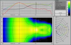
You might want to look more closely at Earls polar response app, and what each line means. 😉Well, I didn't make it up...lol....
Red and Black do not represent the individual responses of the woofer and tweeter, which I suspect is what you're thinking. (Yes its a bit confusing that they are not labelled, I fell for the same thing myself)
From memory Red is power response, Black is directivity index on the chosen axis, and the colour line is the frequency response on the chosen axis. All three measurements are with both drivers active - there are no individual driver measurements in that data that would allow you to determine the crossover frequency.
Don't all the speakers you currently sell have crossovers above 1khz?
The Summa is about 800 Hz, the Abbey about 900 Hz, the Nathan about 1100 Hz and the Harper about 1500 Hz. No 1" tweeter is going to get anywhere near those points at the efficiencies and SPL capabilities that I obtain. Not even close.
From memory Red is power response, Black is directivity index on the chosen axis, and the colour line is the frequency response on the chosen axis. All three measurements are with both drivers active - there are no individual driver measurements in that data that would allow you to determine the crossover frequency.
That is correct. It is explained somewhere, but I forgot where 🙄.
You might want to look more closely at Earls polar response app, and what each line means. 😉
Red and Black do not represent the individual responses of the woofer and tweeter, which I suspect is what you're thinking. (Yes its a bit confusing that they are not labelled, I fell for the same thing myself)
From memory Red is power response, Black is directivity index on the chosen axis, and the colour line is the frequency response on the chosen axis. All three measurements are with both drivers active - there are no individual driver measurements in that data that would allow you to determine the crossover frequency.
Ah, I guess I'm not looking at the charts correctly then, I was thinking that they were driver axis response where we'd be able to guess the crossover point by looking at their roll off. I guess I'll have to get that polar response app and take a closer look.
It would certainly be helpful if the graph was labelled... 😉 Although it's possible to deduce what each line is when playing with the "live" version of the app, its not at all clear from just looking at the static screenshot. I bet the two of us are not the only people to be fooled by Earls graph before. 😀
Why not the Bohlender Graebener Neo3-PDRW Planar Tweeter for most speakers that should be enough performance or for the ultimate we should use Raal ribbon tweeters then??
Why not the Bohlender Graebener Neo3-PDRW Planar Tweeter for most speakers that should be enough performance or for the ultimate we should use Raal ribbon tweeters then??
I love my Neo 3 PDRs but I'm not under the impression that they're the best. Certainly worth their $65 price tag though, at least imo.
Thanks for all this info - much appreciated.The problem with just making a dome twice the size (well one of the problems) is that you only make it more directional at the top end of its range, when it really needs to be made more direction at the bottom end. At the bottom end where you're trying to cross it over with a midrange driver the directivity is still controlled only by the baffle.
A flush mounted dome on a flat baffle will have a full 180 degree radiation angle (albeit perturbed by diffraction effects unless the baffle edges have large radius curves) from its low end up to some frequency where the directivity of the dome itself starts taking over - for a 1" dome this is about 8-10Khz. Above this frequency the radiation will progressively narrow with further increases in frequency.
Doubling the diameter of the dome would at most halve the frequency where it just starts to become more directional than 180 degrees, so the 2" dome would just begin narrowing its pattern at around 4-5Khz. If you were crossing it over at 3Khz or below there will be almost no change in directivity there, (still controlled by the baffle) thus no better directivity match to the midrange driver, and still significant diffraction effects as high as 5Khz or so.
What's more, you've now made it much more directional at the top end, and because the bottom end directivity is still constrained by the baffle you now have a much greater total shift in directivity/power response from the bottom end to the top end than you would for the 1" dome, which may or may not be desirable.
On the other hand, take your same 1" dome and place it in a well designed wave-guide, and the story is very different. Now the wave-guide controls the low end directivity of the driver, constraining it to a set angle, lets say 90 degrees. As long as the wave guide is large enough it can maintain this angle to well below the crossover frequency for the tweeter, helping to achieve a good match to the midrange driver, as well as minimizing diffraction effects.
As frequency goes up the directivity stays much the same until we reach the point where the directivity of the dome itself starts to narrow (8-10Khz for the 1") where it will again narrow progressively.
Directivity is uniform over all but the top octave, and total shift in directivity from the bottom end to the top end is much less than a naked dome of either size. Power handling and maximum SPL at the bottom end of its range (where domes struggle) is greatly improved.
I don't think there's much real science behind those old acoustic "lenses", and that they were a fad of the times.
I've heard speakers with them and wasn't impressed. They're just trying to take the output of a driver that is beaming badly at high frequencies and attempting to deflect it to "increase" the dispersion. Trouble is all the little reflecting surfaces cause a mishmash of reflection and diffraction which really messes up the frequency response. Off axis response might be increased slightly at the expense of a really awful looking frequency response and a peculiar lumpy polar pattern.
Better to start with a driver with the desired dispersion and design from there rather than add a band aid.
This very thorough 1962 Electronics World article is where I learned most about how those lenses operated: "The Acoustical Lens"
Btw during my childhood, one of my parent's friends owned a Sansui/Garrard SuperZero/JBL Century L100 quad system & he kept all the catalogs for JBL speakers, including one for separate drivers. I read them every time we visited and those funky lenses always fascinated me).
I don't think there's much real science behind those old acoustic "lenses", and that they were a fad of the times.
I've heard speakers with them and wasn't impressed. They're just trying to take the output of a driver that is beaming badly at high frequencies and attempting to deflect it to "increase" the dispersion. Trouble is all the little reflecting surfaces cause a mishmash of reflection and diffraction which really messes up the frequency response. Off axis response might be increased slightly at the expense of a really awful looking frequency response and a peculiar lumpy polar pattern.
Look up Bart Locanthi and his early paper on these. Not someone I would accuse of being short on science.
David S.
I'm not suggesting there is no science behind diffraction slots in general, obviously they're used for focusing light and electromagnetic radiation, however in both those applications the relative bandwidth of operation is an extremely narrow percentage of the operating frequency compared to the several octaves a tweeter is expected to cover.Look up Bart Locanthi and his early paper on these. Not someone I would accuse of being short on science.
David S.
What I am suggesting is that the practical implementations of an "acoustic lens" for tweeters back in the day was rather wishful thinking. Show me a cone tweeter of the era with severe beaming without such a lens, then show me that placing the lens in front of it improves the dispersion at high frequencies whilst simultaneously providing a smooth frequency response, clean diffraction free impulse response and a smoothly monotonically falling off axis polar response.
There is no doubt that some increased dispersal of high frequencies will take place, but the drawback is that performance of the lens will vary greatly with frequency due to the fixed size slots, will introduce spurious diffraction and reflection that will cause narrowband ripples in the frequency response and make it impossible to get a clean impulse response.
If you look at the evolution of constant directivity wave-guides, diffraction slots were once considered a necessity of the design, but many years later it was realised that the diffraction from the sharp edge was a serious and under appreciated problem for sound quality and designs evolved to avoid it.
With modern speakers (at least some of them) going to great pains to eliminate sources of diffraction and reflection from the cabinet and mounting, any kind of diffractive grating in front of a tweeter is a big backwards step.
If you're talking about 50 years ago when high quality wide dispersion tweeters were thin on the ground, it might have been a useful band-aid to increase high frequency dispersion - after all the same drivers probably already had a rather ragged treble response to begin with, and you can bet no attention was paid to diffraction in the rest of the speaker and cabinet design.
But with today's modern tweeters which can be both very smooth and wide in dispersion, a diffraction based "acoustic lens" is nowhere near state of the art, so I can see no reason at all to use one.
I did my MS thesis on slant plate acoustic lenses. This was also an AES paper. There is some good theory behind them, but implimentation was always a problem. The plates would vibrate, etc. things the theory did not address. The real measured responsese were never as good as one hoped.
The use of foam in a waveguide was a direct result of an attempt to use the foam as a "lense". It really is a good material in this regard. But I fould that the "lense" effect was less pronounced than the "sonic" effect so I opted to optimize the sonic effect.
The use of foam in a waveguide was a direct result of an attempt to use the foam as a "lense". It really is a good material in this regard. But I fould that the "lense" effect was less pronounced than the "sonic" effect so I opted to optimize the sonic effect.
As long as the horn or waveguide makes it worth going there, it can.I really doubt a 1" CD would be happy at 700hz.
As we do 😉 ..it's under 'Comments' on the default plot in the app.That is correct. It is explained somewhere, but I forgot where 🙄.
I, of coarse, strongly disagree with this. Measurements tell the whole story when you know what to measure and how to interpret them. Having been involved with a myriad of subjective tests, I also know how unreliable subjective assements are. I do (almost) nothing "by ear", everything is based on measurements. My customers and I are happy with that approach.
re seebert "a full set of (as an example) pre or power amplifier specs will not give anyone reading them a good indication of how the unit will perform in their own real world."
That is correct when the specifications are either incomplete or do not represent the way the equipment will be used in the real world. For example, when it comes to power ampilifers (which don't actually amplify power but voltage and have a final stage capable of delivering a lot of current) the standard method inherited from the 1920s and 1930s uses a resistor as a load and measures frequency response at 1 watt output. Real world speaker loads are neither purely resistive nor are they passive. Their reactive components and their back emf can adversely affect some amplifiers and not others. The concept of slewing rate and transient intermodulation distortion stems from the fact that at higher power ouput levels the bandwidth is reduced and FR can be much poorer. If FR were specified at full output and all levels below, TIM and slew rate would be unnecessarily redundant.
The way in which loudspeakers radiate sound into solid space and how that sound interacts with a real room is rarely if ever more than hinted at with lip service. No data is generally published for FR at all solid angles in all planes even at one SPL level let alone at multiple SPLs. There are no commercial loudspeakers which are designed with engineered provisions to control how speakers interact with real world rooms by making provisions to compensate for variables of different rooms so that the end result will be similar performance no matter what room the speaker is installed in. The use of tweeter and midrange controls and equalizers is entirely unsatisfactory because they affect both the direct and reflected sound fields simultaneously, that is they can't be altered independently of one another.
The current design philosophy seems to be to defeat the acoustics of the listening room one way or another through restricting high frequency dispersion, placing speakers far from reflective surfaces, and using sound absorbing material. Short of creating and anechoic chamber, the world's worst place to listen to music, the battle against listening room acoustics is one the speaker designer cannot win.
Last edited:
Several problems with small domes that are inherent in the design.
1) non-controlled directivity going from wide to narrow within their passband
2) low efficiency which means that they will suffer from thermal modulation (dynamics)
3) inability to ever achieve high SPLs without serious overloading (distortion)
4) inability of the crossover to go down below 1 kHz. Crossovers above 1 kHz are a very bad idea.
I can't live with any one of these three, but all of them together is a disaster.
A multidirectional array of tweeters has the following advantages over a single tweeter
1) uniform dispersion over a very wide angle is possible by aiming them in different directions. This is much closer to the way musical instruments propagate sound. Just walk around a piano at a piano bar or a street musician (buskar) and notice how little the tonality changes. This can never be true of single tweeter designs. Multiple tweeters also create multiple comb filters where the the number of peaks and dips are so many and change in what frequencies they occur at so much with slight changes in orientation that for all practical intents and purposes they don't exist. When you are on the direct field of one driver, you're at an angle to all the others. Therefore the total power output versus frequency comes much closer to the FR of the shortest path length for any direction between you and the array. The term "on axis" loses its meaning.
2) An array of tweeters cuts the power requirement into small fractions of what a single tweeter must handle. Efficiency of 90 db for each driver is typical. Dynamic compression is sharply reduced or eliminated. Tweeters rated at 20 to 30 watts can each operate at only a fraction of a watt producing almost no temperature rise in their voice coils.
3,4) Tweeters should be crossed over at a high frequency and their passband in the audible range restricted to no more than 2 to 2 1/2 octaves. That means a crossover no lower than 3500 to 5 khz. A tweeter with a lower crossover must handle too much power at frequencies it is not optimized for. It is nearly impossible to get a 2 way design to cover the entire audible spectrum of 10 octaves. Invariably there is a tradeoff somewhere. Usually it's in the deep bass but often there is an abrupt change in radiating angle at the crossover frequency. Adding a subwoofer turns it into a 3 way system, usually meaning the end user must experiment to get the best possible match up. The 4 way design may seem complex but it allows each driver to cover a range for which it is best suited. Loudspeaker drivers are resonant devices with a useful range of about 2 to 2 1/2 octaves, rarely much more. The only exceptions are headphones but they can only prodice a very small amount of soundpower.
When well executed, the 4 way is probably the system with the fewest crossover points necessary for high fidelity. Use of multiple drivers in each range allows greater design flexibility in angular radiation characteristics and increased power handling.
An inexpensive array of multiple poly dome tweeters easily outperforms the most expensive single tweeter in all significant aspects except one. If you want a tweeter to beam high frequencies at you with few early reflections so that you can listen in a sweet spot and hear some special imaging that only such an arrangement can produce, a multidirectional array of tweeters is not the answer.
This is much closer to the way musical instruments propagate sound. Just walk around a piano at a piano bar or a street musician (buskar) and notice how little the tonality changes.
I don't think our speakers are intended to be stand-ins for instruments, but instead working together to form an image. When listening to music, if I look directly at my speakers they appear to be completely silent. Even when the stereo image places a performer around the location of one of the speakers, it still doesn't sound like it is coming from the speaker. I have only been able to achieve this since paying closer attention to diffraction and reflections, both of which I have improved with narrowed directivity.
I don't think our speakers are intended to be stand-ins for instruments, but instead working together to form an image. When listening to music, if I look directly at my speakers they appear to be completely silent. Even when the stereo image places a performer around the location of one of the speakers, it still doesn't sound like it is coming from the speaker. I have only been able to achieve this since paying closer attention to diffraction and reflections, both of which I have improved with narrowed directivity.
Tonality is one of the four basic elements of music. Imaging is not. For me, if a sound reproducing system cannot reproduce the beautiful tonality of acoustic musical instruments closely to the way they sound in the real world, that system is not high fidelity and whatever other atributes it has are not worth a whole lot.It is the tonality of the instruments which is a crucial element in the appreciation and enjoyment of music. Recording systems invariably come in a poor second at best.
- Status
- Not open for further replies.
- Home
- Loudspeakers
- Multi-Way
- Why Do Most Designs Favor 'Cheaper' Tweeters