If it is a Japanese 70’s device then switch metallurgy is like many Chinese switches today. Despite very nice and sturdy (jealousy inducing even!) build quality their switch knowledge was not sufficient (yet) then.
Last edited:
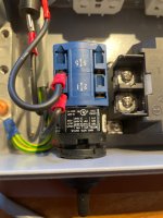
Here is the datasheet for the 40A relay the OP used.I replaced the power switch on an old 70's receiver and added a 40A relay (40mA coil) to preserve the switch from burning out again.
https://www.citrelay.com/Catalog Pages/RelayCatalog/J115F3.pdf
Last edited:
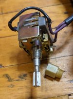
I would have to remove some components to get a good shot of it, but it's an old Alps rotary switch. As stated previously, it uses a cam to open and close so there's no sliding of the contacts. The replacement was supposedly a NOS(new old stock) which would explain the oxidation. I know what the inside looks like because I teased apart the old one and tried to save it but the contacts were too burnt.if you show a picture
As written the Japanese did not have the knowledge yet to make good switches. So the NOS replacement is likely of the same quality.
Is it a rotary switch with just 0 and 1? Won’t a replacement by a good brand not be a solution? I stock Kraus & Naimer rotary switches that keep working OK.
Is it a rotary switch with just 0 and 1? Won’t a replacement by a good brand not be a solution? I stock Kraus & Naimer rotary switches that keep working OK.
Last edited:
OK, for clarity I pulled it out and took some pics.Is it a rotary switch with just 0 and 1? Won’t a replacement by a good brand not be a solution? I stock Kraus & Naimer rotary switches that keep working OK.
Yes, just a 0/1 is all I need. Originally it was a 4 position with one section for power and the other for speaker selection. I removed the speaker section because I'm not running them through it anymore for obvious reasons.
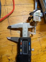
That beige plastic piece holds the switch to the chassis and the threads on the opposite end are what hold the faceplate on, so I have to use it. The bushing thread is an M9 and the shaft is 6mm.
Attachments

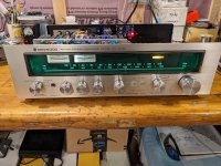
That is a known old type. Now how does the receiver look (size/color of knobs, space for another switch)?
If the loudspeaker contacts were also on their way out you are sure it is the metallurgy being not up to its task.
If the loudspeaker contacts were also on their way out you are sure it is the metallurgy being not up to its task.
Almost certainly the metallurgy is not up to the task, hence the relay. The power and speaker switches on these old stereos commonly fail.
Not sure what you mean by space for another switch but drilling the faceplate is not an option. I want the original look even though internally it's not.
Not sure what you mean by space for another switch but drilling the faceplate is not an option. I want the original look even though internally it's not.
Attachments
Ok, I understand. I have done such repairs but my primary concern is reliability. So I take the liberty to change to good switches that fit physically. The "wrong" text can also be eliminated. Better an old device that works as having to work repeatedly on an old device. When not finding a rotary switch that fits I would even use 1835 rectangular rocker switches as these fit with some filing. My default rotary switch is a 4 pole 90 degrees 45 degrees NOS/NIB version of Kraus & Naimer CG4 with rounded "audio like" knob.
The Lorlin RMS1035 also comes close but the "feeling" is not what you want I think. Choose carefully as many versions exist.
https://lorlinelectronics.co.uk/wp-content/uploads/2024/05/RMS-Datasheet-May-2024.pdf
This one which I never used seems a direct replacement:
https://www.audiophonics.fr/en/swit...able-rotary-switch-on-off-250v-4a-p-6670.html
Last edited:
I appreciate the feedback.
The m9 bushing really limits my options. Going to see if a new spacer piece can be made that will screw onto an m8 bushing, then I will have some options.
The m9 bushing really limits my options. Going to see if a new spacer piece can be made that will screw onto an m8 bushing, then I will have some options.
Why exactly? It can be drilled/filed larger isn't it? Is the faceplate solely mounted by this M9 bushing?
The bushing of the switch is m9. The plastic spacer screws onto that bushing to hold the switch to the chassis. The opposite end of the spacer is what the faceplate screws to.
There must be other points like the other potentiometers or switches where that faceplate also is connected. A new rotary switch can also clamp that faceplate to the chassis. Not with that bushing (I think I still have brass ones of those) but with the new switches system. Some rotary switches can be screwed with 2 x M3 screws that can also clamp that faceplate. There is always a possibility. If you make a picture of the situation advice can be better.
A countersunk M3 screw hidden by the knob to keep the faceplate where it should be also is a possibility. Maybe with the help of an M3 brass standoff in between. Then the focus is how to mount the new switch (probably only to the faceplate) while having the correct length of the axle.
The usual dilemma: do I want it to be good and reliably working (plus: time and effort level higher) or do I want it to look original? As earlier written I forgot about the "original" long ago as it means you will meet the device twice for repair and you'll be repairing with error prone parts too. When much deviating from original the new looks may be even appealing 😉 With that total freedom one does not need to recall brands or type numbers of devices etc. as it is solution oriented and just another broken device. I recall such a device where 4 holes were drilled at the corners to keep the scratch free faceplate mounted with stainless steel M4 Inbus bolts and washers.
Last edited:
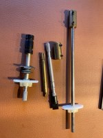
My standard 10A rated rotary switch due to space constraints manually modified to only 2 decks (it has normally 4 decks). It has 2 x NO and 2 x NC contacts which sometimes are handy for stand-by lighting and such.
Switches like these practically can always be made to fit. Even when mounted on a metal plate with an extension rod (depending on the chosen type) and the cut off original knurled axle of the old one. With the original knob! Original looks but better executed.
Switches like these practically can always be made to fit. Even when mounted on a metal plate with an extension rod (depending on the chosen type) and the cut off original knurled axle of the old one. With the original knob! Original looks but better executed.
Attachments
Last edited:
@delverboy , leave that original switch in front, but don't connect it. Remove the 40A relay from the device. Drill a hole in the back near the power cable and put in some stronger dual Kipp (or Wipp) switch 10 or 16A to break neutral and phase. Bridge its contacts with 10nF 275VAC PP X2 capacitors. And there will be no more problems.
Last edited:
Think in possibilities while retaining normal functionality preferably with much improved (or even definitive) reliability.
The knurled axle really is least difficult of the challenges. Metal reworking is Zen for the soul but Confucius warned to avoid stainless steel 😉
The knurled axle really is least difficult of the challenges. Metal reworking is Zen for the soul but Confucius warned to avoid stainless steel 😉
Attachments
Last edited:
An extension rod, I like that idea!
I should be able to attach to the shaft of the existing switch by removing the rear portion. Will need to mount a bracket to support the new switch. Eliminating the relay would be great.
There's not allot of room but I think I can make that work.
I should be able to attach to the shaft of the existing switch by removing the rear portion. Will need to mount a bracket to support the new switch. Eliminating the relay would be great.
There's not allot of room but I think I can make that work.
Don't break the switch. I think I saw somewhere that it can be bought all together as a set. Ali or ebay.


- Home
- Amplifiers
- Power Supplies
- Why did this relay fail so soon?