The Decware schematic shews SV83s. The cathode connexions are slightly different than the EL84. Check it out. Not always plug-in compatible🙂
I am following Decware and the other users saying this is EL84 compatible with no caveats. As I recall, this is a EL84 amp...they Decware later decided sounded better with this other tube and included it as standard. I cannot speak to what was modified or not. There are no other reports I can find of incompatible EL84s. While I know every tube is different, there is no caveats given my the manufacturer or users. I am not going to die on this hill defending that statement, but I am following the facts presented to me, and what issue this caused (and other EL84s work fine).
Decware UFO2
The schematic posted above is not the OP's amp. the schematic is for the Taboo, which is a SE pentode design. I don't know how to post photos, but the schematic for the SE84 series is readily available. The amp has a long history of compatibility with the EL84.
Before I did the CCE mod on my SE84B, I preferred the EL84 types to the SV83. Once I did the mod however, my preference changed to the SV83 ( 6p15p-ev ).
I may have missed it, but I have never heard of anyone having a compatibility problem with an EL84 and the SE84 series of amps. And I have been hanging on the forum for a long time.
Cheers, Crazy Bill
What is not up for debate is if the amp works with all those tubes. What is up for debate is why certain EL84s (most EL84s) work, but why these did not...if they are in fact EL84s.
I suspect its maybe to do with bias type.
Cathode bias is self setting so is tolerant of different tubes.
Fixed bias isnt so tolerant.
Cathode bias is self setting so is tolerant of different tubes.
Fixed bias isnt so tolerant.
JH Stewart
No one said the tubes are identical, but that they were interchangeable and compatible in Steve's circuit. And they are.
The suppressor grid and the cathode are internally strapped in the EL84 types, while in the SV83 types they are not and the suppressor grid is accessible via pin 1 and 6. This difference has nothing to do with whether they are compatible in this circuit.
A while back I bought a bunch of EL83 types, thinking they were interchangeable with the SV83 and I wanted to give them a listen. They are not interchangeable. I plugged in a pr and got exactly what is being described here. Very low volume and distortion.
Who knows ?
Good luck
Last edited:
Just Another Debate
Traveling rapidly in ever decreasing circles until disappearing into its rear orifice & reappearing in another dimension!😀
Traveling rapidly in ever decreasing circles until disappearing into its rear orifice & reappearing in another dimension!😀
Internal connections vary on EL84s - if the amp is wired to use 6P15 / SV83, MOST EL84s will work. 7189As will definitely not work in a SV83 socket, though they'll work in an EL84 socket if pins 2, 6 & 8 aren't wired.
I wonder how many EL84s have been trashed when a "shorts" test came up on one of the "unused" pins.
I wonder how many EL84s have been trashed when a "shorts" test came up on one of the "unused" pins.
Tom,
This brings back a sad memory. Long time ago, I personally trashed a quad of 7189as after they showed shorts on my tube tester. The tester did not have settings for 7189a, so, naturally I tested them as EL84s.
This brings back a sad memory. Long time ago, I personally trashed a quad of 7189as after they showed shorts on my tube tester. The tester did not have settings for 7189a, so, naturally I tested them as EL84s.
Rusky 6n14p-ev
+1
What does a UFO look like underneath? Got the circuit?
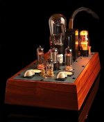
DECWARE / ZEN TRIODE ANNIVERSARY AMP model SE84UFO25
dave
Attachments
Decware Schematic
Changes with the phase of the Moon.
Built for Show, not Go.
Changes with the phase of the Moon.
Built for Show, not Go.
Attachments
Last edited:
The SMPTE Test
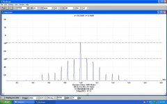
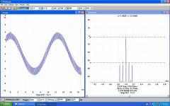
The Society of Motion Picture & Television Engineers is/was a very common test used to evaluate the quality of reproduction of sound amplifiers. Two signals, one low frequency & another at the other end of the audio spectrum are applied to the input of the amplifier & the distortion in the output measured. This kind of test is much more difficult for an amplifier (or other network) than a simple single frequency THD test.
The low frequency signal was usually 50 Hz or 60 Hz depending upon the location of the test, it was simply derived from the local power system in the test set. The high frequency signal was created by a simple oscillator on board. 5 to 8 KHz works well. Because of the way the test set worked the quality of the test signals was not very important. The result is an indication of the Intermodulation Distortion (IMD) created in the amplifier. Heathkit & others marketed IMD testers, quite a few are available on the used market.
To do this test I use an LF of 80 Hz from an HP 200CD. That way it is possible to see intermods caused by the PS at the PS fundamental & its harmonics, 60, 120Hz & so on. I used HF of 5 KHz from a GW GAG-810. They are combined in a simple resistive network.
I ran a Decware clone on the test bench, the IMD was 9.74% while the output was 260 mWatts. The Decware amp always clipped at less than one Watt.
For a point of comparison I pulled an all 2V tube PP 33s of the shelf & ran the same test. At 820 mWatts the IMD was 2.67%. The PP 33 Amp clips at ~4.8 Watts.
On a scale of Zero to 10 this version of the Decware amp might get a two from the Geezers of the 50s & 60s. But others today can decide for themselves.🙂
Attachments
Last edited:
Changes with the phase of the Moon.
Built for Show, not Go.
Looks very similar to the original iteration.
dave
I bought 2 sets (4 total tubes) of these to add some variety to my tube collection:
Ei 6BQ5 / EL84 – Upscale Audio
I have a Decware UFO2 and it is compatible with EL84s, and I have used other EL84 tubes in it, no issue, this amp begs for tube rolling.
The ones in the link arrived in the mail, popped them in, and the volume was MAYBE 5% what it should have been, and what was there was muffled and muddy (100% useless, there was just 'something' barely playing). Tried the other two, same thing. Long story short, either they are not compatible or they all happen to be defective.
Any idea? Why would they fit, properly heat up (heaters came on as expected), play 'something' but not work? No biasing in the amp...and they work fine with a range of EL84s.
They will be going back tomorrow, but now I have zero confidence in buying other EL84s because I have no idea what was happening.
Thanks!
Do you have an emission tester? Maybe test one of the upscale tubes against an EL84 you know works, with all the tester settings the same. You got sound, just very weak, and the tube is the same tube number you know works in that amp. Don't know why anyone would suspect an incompatible pin out without first testing the tube.
No tester - tubes are on the way back to Upscale.
What does it suggest if the meters were reading 'normal' but no sound? Not like they didn't heat up, blow up, or do nothing - they seemed to be 'working' (at least the heaters!)
What does it suggest if the meters were reading 'normal' but no sound? Not like they didn't heat up, blow up, or do nothing - they seemed to be 'working' (at least the heaters!)
You wrote: "...though they'll work in an EL84 socket if pins 2, 6 & 8 aren't wired.". I think that "2" is a typo and should be "1", since pin 2 in an EL84 is always connected to its control grid.Internal connections vary on EL84s - if the amp is wired to use 6P15 / SV83, MOST EL84s will work. 7189As will definitely not work in a SV83 socket, though they'll work in an EL84 socket if pins 2, 6 & 8 aren't wired.
I wonder how many EL84s have been trashed when a "shorts" test came up on one of the "unused" pins.
To support what you and jhstewart9 already wrote an application note by Svetlana on the SV83. See especially items 1 and 4. The claim/suggestion in the manuals of Decware that their amplifiers can take both SV83 and any EL84's, just isn't right since these amplifiers don't have the switch to disconnect pin 6 from pin 3 as decribed in item 4 of the application note.
Using the SV83 in EL84 Amplifiers
The Svetlana SV83 is a 12-watt power pentode which is well-suited for audio use, in either guitar amps or in high-fidelity equipment. Its original design, intended for high-accuracy video amplification, gives the SV83 high transconductance and very high linearity. The SV83 may be used in any EL84 or 6BQ5 circuit, provided that some changes are made as described below, in items 1 thru 4.
1. There is a small difference in the pinout of the SV83 versus the EL84. SV83s may not have their suppressor grid connected to the cathode internally. To insure the usability of all SV83s in an EL84 socket, do the following:
a) Insure that pins 1 and 6 of each SV83 socket are NOT connected to any circuitry, nor used as a tie point for components.
b) On each SV83 socket, connect pin 6 to pin 3, using a short wire jumper. Be sure the wire does not touch any other circuitry.
(Note: there is an issue with the pinout of SOME EL84s versus the SV83. See item 4 below.)
2. The SV83's screen grid (pin 9) is not able to accept an operating voltage of more than 200v DC. Because nearly all EL84 amps operate their screen grids at or near the plate voltage (in pentode, ultralinear or triode connection), the amplifier must be modified to provide a lower voltage to the SV83 screen grids. If triode connection is desired, the plate supply voltage must be limited to 200v DC. For higher plate voltages, any of the following circuits will work:
a) Figure 1 is probably the lowest-cost method of deriving a screen voltage. This works adequately for most guitar amps and some vintage hi-fi amps. The screen voltage can "sag" when full power is reached, although this may not be an issue, especially in a guitar amp. A major advantage of this scheme is that the resistive divider also acts to discharge the power-supply filter capacitors when power is turned off. This circuit may be used with a single SV83 or one pair of SV83s. It adds about 15-20 mA of current drain to the plate supply, which must be allowed for in the power transformer.
b) Figure 2 is the best solution for high-end audio design. The zener diodes are a low-cost option which offer good regulation and good stability. The types shown are rated for 1 watt dissipation and are operated conservatively here. A filter capacitor may be paralleled across them to assist regulation if desired. Using the 0A2 gas regulator tube is a possible all-tube technique to achieve the same result. Although 0A2s are out of production, they are long-lasting and readily available in bulk quantities as NOS. Gas tubes can NOT be used with a parallel capacitor larger than 0.1 uF, as zeners can. The choice of which regulation method to use is up to the designer. This circuit may be used with any number of SV83s up to a quad.
3. Bias adjustment may be necessary to obtain the same plate current with SV83s as with EL84s. Typically the SV83 will require about 1-5v less negative grid voltage than EL84s for the same idle point, due to the higher transconductance and sensitivity of the SV83. If cathode bias is used in the amp, the cathode resistor may be decreased in value about 20%. The designer is urged to equip the amplifier with SV83 and try it without bias adjustments, as the resulting bias value may be acceptable. No modifications to driver circuits are required.
4. An amp which is modified to accept SV83s can be made back-compatible with EL84 types. First, a switch must be provided to DISCONNECT pin 6 from pin 3. (This is necessary because SOME EL84 and 7189 types have internal connections to pins 1 and/or 6. Many EL84s do not. This can cause some confusion.) Second, the idling plate current of the EL84 will be lower in the SV83-modified circuit. The switch above may use a second pole, whcih can be equipped to switch in different cathode-bias resistors. The switch can then be set to allow proper operation.

Thanks for the late reply.
I can confirm the new product JJ EL84 works fine in the amp, which added to the mystery.
I can confirm the new product JJ EL84 works fine in the amp, which added to the mystery.
The use of the word "mistery" probably means that you still don't understand what could have been going on with your EI 6BQ5/EL84's.
Most SV83's have their suppressor grid connected to pins 1 and 6, but not internally to pin 3 (cathode). So a socket that is supposed to take a SV83 must be wired so that pin 1 and/or pin 6 is/are connected to pin 3 (cathode).
The EL84 has its suppressor grid internaly connected to its cathode. So for EL84's a socket doesn't need to be wired so that pin 1 and or pin 6 is/are connected to pin 3 (cathode).
It is known that some EL84's 'from the old days' have internal connections to pins 1 and/or 6.
If for instance pin 6 in your Ei 6BQ5/EL84's was internally connected to pin 2 (control grid), than because of the wire between pin 6 and pin 3 on the socket, the cathode got connected with the control grid. This would mean there was no bias. The lack of bias would make the current go up but because of the cathode resistor the voltage drop over the tube itself would go down, more or less preventing the tube to 'take off completely'. I would think that under these condtions you would still hear something coming out of the amp but it would be far from normal (like you described in post #1).
There are more tube types 'from the old days' of which the internal connections to some of their pins differ between manufacturers. This is what I experienced when testing EL36/PL36's of different brands/manufacturers:
Configuration 1
Philips, Pope, Adzam, Siemens, Mullard (manufactured by Philips, La Radiotechnique, Mullard, Valvo)
Pin 4 (screen grid) internally connected to pin 1
Pin 8 (cathode) internally connected to pin 3
Configuration 2
Telefunken (manufactured by Telefunken)
Pin 4 (screen grid) internally connected to pin 3
Pin 8 (cathode) internally connected to pin 1
Configuration 3
RFT, Haltron, Teonex (probably manufactured by RFT)
Pin 4 (screen grid) internally connected to pin 1
Pin 8 (cathode) not connected to any other pin
Pin 3 is not connected to anything
Last edited:
I've the same issue with Decware amp and a pair of Telefunken El84s: the sound is small and muddy.
After read your detailed replies,I a newbie learned something,many Thanks! It seems about 'Internal connections vary on EL84s',that is to say pin 1,pin 6,pin 8. So if tube pin 1&6&8 coould be floated, then the socket pin6 to pin 3 connection be bypassed,could it work?Such as through a straight adapter that make socket pin and tube pin connect directly for pin 2&3&4&5&7&9, but disconnect pin 1&6&8 inside the straight adapter.
After read your detailed replies,I a newbie learned something,many Thanks! It seems about 'Internal connections vary on EL84s',that is to say pin 1,pin 6,pin 8. So if tube pin 1&6&8 coould be floated, then the socket pin6 to pin 3 connection be bypassed,could it work?Such as through a straight adapter that make socket pin and tube pin connect directly for pin 2&3&4&5&7&9, but disconnect pin 1&6&8 inside the straight adapter.
- Home
- Amplifiers
- Tubes / Valves
- Why did this EL84 not work in my Decware amp?