What makes your scenario odd is that for a static DC fault to cause this would need one of the output devices to fail open circuit in the base/emitter path and that isn't a common failure mode. Usually transistors fail short circuit..
Output transistor are in short circuit :/ I checked again (and again), I don't see anything wrong on the output that it can destroy the transistors. I only attached a 4R speaker.
Caps can explode for a few reasons.
1/ Incorrect polarity.
2/ Too high voltage.
3/ Just a bad capacitor.
4/ Old age.
1/ Impossible, I re-used the driver PCB without modifying
2/ I re-used the transformer from the AVR
3/ Possible, but not very old (5 years)
4/ 5 years
I replaced the defectives parts yesterday, add the 100n cap on the ouput, replaced the fuses by 10R 1/4W resistors for the first start, and add 2x100R resistors between the 0.22R and the multimter for measure the bias. This last point is describe in the manual service of the SR606 (it is a same topology ..)
An externally hosted image should be here but it was not working when we last tested it.
Last edited:
For 4 ohms (in practice it may be 3 ohms or less), one pair of output transistors is not enough. We need 2-3 pairs.
61.5/4(3)=15(20)A 2SC5242, NPN 230В 15А
61.5/4(3)=15(20)A 2SC5242, NPN 230В 15А
Last edited:
Output transistor are in short circuit :/ I checked again (and again), I don't see anything wrong on the output that it can destroy the transistors. I only attached a 4R speaker.
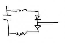
If you look at the equivalent circuit for the output stage you have the cap across what are effectively two diodes. These 'diodes' are the B-E junctions of the output devices and mean that as long as the junction is intact (including being short circuit) then no significant voltage can build up across the cap to cause failure.
Attachments
For 4 ohms (in practice it may be 3 ohms or less), one pair of output transistors is not enough. We need 2-3 pairs.
61.5/4(3)=15(20)A 2SC5242, NPN 230В 15А
I used the 4R speaker only for test, and it is a 30W speaker 🙂
The final speakers are 6R and 8R.
If you look at the equivalent circuit for the output stage you have the cap across what are effectively two diodes. These 'diodes' are the B-E junctions of the output devices and mean that as long as the junction is intact (including being short circuit) then no significant voltage can build up across the cap to cause failure.
But if one driver failed, it can... no ?
No. If one driver failed you would have (depending which driver) a high positive or negative voltage applied to the cap but the cap still sees little voltage across it. The B-E junctions of the outputs act as a clamp.
Something else would need to fail as well for the cap to see a high voltage.
Something else would need to fail as well for the cap to see a high voltage.
Why not build the amp up again and this time run it carefully using a bulb tester in the power supply.
It is my next step 😀
I have mounted two 10ohms resistors instead of the fuses, if something is wrong, the resistors will burn, not the transistors 🙂
I will test this tonight if I have the time .
I have mounted two 10ohms resistors instead of the fuses, if something is wrong, the resistors will burn, not the transistors 🙂
I will test this tonight if I have the time .
OK 🙂 but the bulb is a good option and non destructive. It would allow you to 'see' and take measurements if something bad starts to happen.
Good luck.
Good luck.
I will check if I have a bulb too, but I'm in France, and these bulbs are stoped due to the "ecological idea"... 🙄
#22 SOA.
You can turn off the collectors Q6050,6060 and check the operation of the drivers (no load).
You can turn off the collectors Q6050,6060 and check the operation of the drivers (no load).
Last edited:
#22 SOA.
You can turn off the collectors Q6050,6060 and check the operation of the drivers (no load).
By removing ?
This is an initial build by an amateur. It is quite likely a bad solder joint is causing a large DC voltage on the failed cap. not a failure of a driver transistor open (which would be rare). OP needs to measure DC voltage at the position of the failed cap, both positive & negative terminal.No. If one driver failed you would have (depending which driver) a high positive or negative voltage applied to the cap but the cap still sees little voltage across it. The B-E junctions of the outputs act as a clamp.
Something else would need to fail as well for the cap to see a high voltage.
Reason I suggest new builders build speaker capacitor amps first like AX6, to avoid damage to speakers with the unreliable solder joints they make. Major DC voltage on output can result from many bad solder joints on direct connected transistor amps.
The possible oscillation OP can't check for without a scope is another issue. It is possible to check for that with a $25 analog VOM, but through a tedious procedure. First one detects a significant AC voltage though the .047 uf cap one uses series the ground lead on an analog VOM to eliminate false indication from DC voltage. Then one proves it is ultrasonic by changing to a 270 to 390 pf disc cap, which ultrasound will pass through but audio frequency AC will not.
Depending on the circuit, you can often just pull the outputs and run into a high z load (headphone jack) directly off the drivers. It doesn’t look like this one can because of the location of the speed up network. In those cases, disconnect the output stage collectors (or install 100 ohm resistors temporarily in series). That will limit any fault current, especially if a light bulb limiter is not an option. You really just need to have one if your friends sneak some into the country, and only use them for this. It is far easier than any other workaround. Even using a variac can result in start up problems. I use both, often simultaneously.
As far as the SOA goes, even using the bare minimum bean counter formula for resistive load (vcc^2/(4*RL)) the dissipation can hit 116 watts. It doubles into a 60 degree reactive load, but the duration of those events is short so it *usually* survives. One transistor pair is barely enough for 8 ohms, as the only wiggle room left for temperature derating is whatever lift on SOA you get from pulse (AC) operation. Run it too hot and you’re playing with fire. 4 ohms might kill it before anything even heats up as you’re starting in the 200 watt peak dissipation range.
As far as the SOA goes, even using the bare minimum bean counter formula for resistive load (vcc^2/(4*RL)) the dissipation can hit 116 watts. It doubles into a 60 degree reactive load, but the duration of those events is short so it *usually* survives. One transistor pair is barely enough for 8 ohms, as the only wiggle room left for temperature derating is whatever lift on SOA you get from pulse (AC) operation. Run it too hot and you’re playing with fire. 4 ohms might kill it before anything even heats up as you’re starting in the 200 watt peak dissipation range.
On the dim-bulb tester or DBT, don't forget that there are refrigerator and oven bulbs that must be incandescent, glass bulb types at the temperatures they are used and still run from mains AC. Though the power ratings are low, a few of these 15W rated types in parallel do the trick for a single channel or both for small, say 2 x 30W amplifiers.
In this country at least, there are still a couple of halogen type incandescent bulbs marketed by Philips that are available and rated at about 50 and 70W. They are priced up closer to LED lamps now but still legal for domestic lighting and just fine for our occasional purpose.
Even so, these are mains powered devices and you should familiarise yourself with local safe mounting and wiring practice if you expect to live a long and healthy life. Don't skimp on safety, if not for yourself, consider kids and other family members who may well be playing with your toys when you aren't around!

Some news :
- I replaced the output transistor
- I replaced the driver 2SA
- I replaced the 47uF explosed
- I tested the others transistors on the PCB driver
- I added a bulb on the 220V
- I added the 100n cap on the output (between OUT and GND)
- I replaced the fuses by 10R 1/4W resistors
- I meseared the bias on the foot of the 0.22R resistor via 2x100ohms resistors (as explained in the manual service of the Onkyo)
- and I plugged the power supply...
BOOM !
No, it's a joke xD
No smoke, the bulb ligh up for 1-2s and decrease to a small light (due to PSU caps loading so).
I adjusted the bias to arround 12mV (it was to 0mV before).
DC offset is 10-11mV
The amp was running for 15min without problem. Output transistor are a little more than "cold", but there is a big heatsink !
The PSU voltage with the bulb is arround 42V.
Now what is the next step ?
- Home
- Amplifiers
- Solid State
- Why capacitor explosed ?