Ok here is the problem. i thought i would use my sound card as a function generator for testing amplifiers and so-on. well life is not that easy.
first of all let me explain the system. i have an EMU 0404 which is my main card for almost everything. the onboard Analog devices soundmax output is plugged into the input of the 0404. thats just because i need the crappy pc mic input for certain things and the 0404 has no mic preamp
anyways i looked at a 1khz wave from the EMU with a scope and i got this. (see attachment)
this is recorded at 44.1 khz, but it does the same thing at up to 192khz but the ringing is much higher frequency.
it doesnt look like normal ringing anyways, it has "reverse ringing" before the transitions as well.
i tried other things as well.
1: soundmax output bypassing emu to scope (same )
2: i thought it might be my cables which are rather long but tried them with the scopes internal square wave reference and it still looked perfect.
Attachments
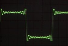
just to be sure, i took the output of the soundmax and viewed it on a software scope that was using the EMUs input. now you can see it on the still pic, but (maybe because of the drift between the 2 cards oscillators) the ringing would cycle between out of phase, cancelled out, and in phase.
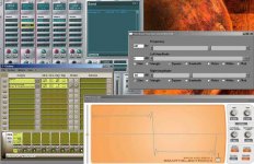
in case you want to know what the programs are,
chainer is free, if you do not want to save presets. it lets you load VST and VSTi plugins directly without a host sequencer.
function generator lite is a rather limited but functional function generator. it is free
exoscope is a free scope vst plugin
anyways, does anyone know how i could fix it? the only way i can think of is to run tests at 192 KHZ and then put just the right capacitor/filter across the output. why are both sound card outputs like that? it is rather annoying now i might have to build a function generator.
Attachments
hi neutron7,
Pre-ringing or "reverse ringing" is characteristics of FIR filters (use google or something for explaination).
Chips on your audio card has FIR filters included, and probably, he has this behaviour. This means that you cannot obtain "clean" pulse from your audio card.
If you test audio amplifiers, also good can be wavelets, you can try this
This is a four period Hann type wavelets, "video edition" 🙂
Best regards,
boggy
neutron7 said:Ok here is the problem. i thought i would use my sound card as a function generator for testing amplifiers and so-on. well life is not that easy.
first of all let me explain the system. i have an EMU 0404 which is my main card for almost everything. the onboard Analog devices soundmax output is plugged into the input of the 0404. thats just because i need the crappy pc mic input for certain things and the 0404 has no mic preamp
anyways i looked at a 1khz wave from the EMU with a scope and i got this. (see attachment)
this is recorded at 44.1 khz, but it does the same thing at up to 192khz but the ringing is much higher frequency.
it doesnt look like normal ringing anyways, it has "reverse ringing" before the transitions as well.
i tried other things as well.
1: soundmax output bypassing emu to scope (same )
2: i thought it might be my cables which are rather long but tried them with the scopes internal square wave reference and it still looked perfect.
Pre-ringing or "reverse ringing" is characteristics of FIR filters (use google or something for explaination).
Chips on your audio card has FIR filters included, and probably, he has this behaviour. This means that you cannot obtain "clean" pulse from your audio card.
If you test audio amplifiers, also good can be wavelets, you can try this
This is a four period Hann type wavelets, "video edition" 🙂
Best regards,
boggy
It's normal that a soundcard used as signal generator gives that result, very evident on the square wave. This is because the impulse responses of normal DAC chips used in soundcards (and in all digital devices) are of this kind:
The explanation involves digital signal processing theory and remember also that the soundcards have a limited bandwidth, while a perfect square wave (with all its harmonics) would require infinite (or at least very large) bandwidth.
You can observe that a lower frequency square wave generated with your soundcard will be more similar to ideal case, since you have more harmonics in the bandwidth allowed (about half of your sample rate).
If you need a perfect square wave you must use a signal generator and not a soundcard. There are chips like the MAX038 that allow to build a signal generator with few components.
An externally hosted image should be here but it was not working when we last tested it.
The explanation involves digital signal processing theory and remember also that the soundcards have a limited bandwidth, while a perfect square wave (with all its harmonics) would require infinite (or at least very large) bandwidth.
You can observe that a lower frequency square wave generated with your soundcard will be more similar to ideal case, since you have more harmonics in the bandwidth allowed (about half of your sample rate).
If you need a perfect square wave you must use a signal generator and not a soundcard. There are chips like the MAX038 that allow to build a signal generator with few components.
a perfect square wave has infinite bandwidth
a soundcard does not have infinite bandwidth... you'll never get a perfect square wave out of ya sndcrd.
but if ya bandlimit the sqaure wave before the go to Dig to analog conversion, you'll loose the ringing, but you get rounded edges.
a soundcard does not have infinite bandwidth... you'll never get a perfect square wave out of ya sndcrd.
but if ya bandlimit the sqaure wave before the go to Dig to analog conversion, you'll loose the ringing, but you get rounded edges.
Hi tchrama,
Ringing in impulse or step response is already a product of band limited network, and ringing, or not ringing, impulse edge depend on Q factor of low pass filter employed in band limiting process.
Especially, pre ringing is relatively rare behaviour, and it's characteristic of FIR filter impulse or step response, for example.
Best regards,
boggy
tschrama said:a perfect square wave has infinite bandwidth
a soundcard does not have infinite bandwidth... you'll never get a perfect square wave out of ya sndcrd.
but if ya bandlimit the sqaure wave before the go to Dig to analog conversion, you'll loose the ringing, but you get rounded edges.
Ringing in impulse or step response is already a product of band limited network, and ringing, or not ringing, impulse edge depend on Q factor of low pass filter employed in band limiting process.
Especially, pre ringing is relatively rare behaviour, and it's characteristic of FIR filter impulse or step response, for example.
Best regards,
boggy
thats all very dissapointing news and shows my ignorance digital audio. i will forget this idea and go with the MAX038 suggestion from paologatto.
thanks everyone for the replies.
thanks everyone for the replies.
Hi,
The ringing is a result of the sharp band limiting itself at 20 kHz. It has nothing to do per se with “digital” or “FIR-filters”. If you mange to build a steep analog filter at 20 kHz you get the same ringing when fed with a square wave.
If you want a good square wave, use a simple NE555. But be careful when testing amps with it, most amps cannot handle it and are not designed to handle such steep edges. It is wise to use a 100 kHz (or lower) 1st order low pass to gently limit the bandwidth of the square.
Cheers 😉
well i wanted sine and triangle and other waveforms as well as music, i was just using the square wave as an example. thats why i wanted to use the PC sound card and not a simple 555.
anyways that maxim ic looks pretty good. I ordered one allready.
anyways that maxim ic looks pretty good. I ordered one allready.
Yes, the Max038 is really nice.. I builded a signal generator with this schematic:
and is very useful.
I added also a frequency meter, done with a single PIC, with this schematic:
loading on it this code:
http://home.datacomm.ch/str/micro.html
(search for "Autoranging frequency meter")
The final device is this:
An externally hosted image should be here but it was not working when we last tested it.
and is very useful.
I added also a frequency meter, done with a single PIC, with this schematic:
An externally hosted image should be here but it was not working when we last tested it.
loading on it this code:
http://home.datacomm.ch/str/micro.html
(search for "Autoranging frequency meter")
The final device is this:
An externally hosted image should be here but it was not working when we last tested it.
Hi Pjotr,
I'm talk about pre-ringing behaviour.
Ok, but you cannot have pre-ringing with an ordinary analog filter. Comb-filter (or FIR) analog or digital has pre ringing in response.
Pre ringing means that signal "ring" before "apearance".
Pjotr said:Hi,
The ringing is a result of the sharp band limiting itself at 20 kHz. It has nothing to do per se with “digital” or “FIR-filters”.
I'm talk about pre-ringing behaviour.
If you mange to build a steep analog filter at 20 kHz you get the same ringing when fed with a square wave.
...
Ok, but you cannot have pre-ringing with an ordinary analog filter. Comb-filter (or FIR) analog or digital has pre ringing in response.
Pre ringing means that signal "ring" before "apearance".
square wave
The ringing is caused by the fact that you are in frequency limited digital domain.
For example, if you simply burn test tones onto a CD they are going to have that ringing. I've done this, feel free to download some very long tones at my site, Part Time Projects. You can see that sine waves come out great, but square waves ring-- its caused by the A/D and D/A converters.
hi , from that said it comes that if you use a non OS and no filter DAC , you don't have anymore ringing . and that's the case there's a lot of cheap non OS DACs you could use through the SPDIF out .
Re: square wave
No, that depends on the CD player you use. I have made test CDs myself with square waves that are not frequency limited or otherwise manipulated, and ringing shows up with some CD players and not with others. This is empirical experience. My understanding of transform theory is unfortunately too limited to explain this.
lgreen said:The ringing is caused by the fact that you are in frequency limited digital domain.
For example, if you simply burn test tones onto a CD they are going to have that ringing.
No, that depends on the CD player you use. I have made test CDs myself with square waves that are not frequency limited or otherwise manipulated, and ringing shows up with some CD players and not with others. This is empirical experience. My understanding of transform theory is unfortunately too limited to explain this.
That's why Non-Oversampling DACs are so populair I guess, you can avoid the pre and post ringing, maybe that's what happend.
I can make perfect square waves with my NonOverSamp DAC at least, using Goldwave for creating the .files and burning the CD with nero.
However, a proper CD player should avoid any frequency content that can not be coded by the sample frequency. So a proper Cd player should have pre and post ringing.
to obtain perfect square from "software" signal generator, you should think about simple "shaping" circuit. i guess, simple triggering of standard CMOS gate by soundcard signal should possess quite fair square? or you can use window comparator circuit or something similar...
Of course you can have pre-ringing on an analog filter!Ok, but you cannot have pre-ringing with an ordinary analog filter. Comb-filter (or FIR) analog or digital has pre ringing in response.
Pre ringing means that signal "ring" before "apearance".
You cannot have ringing appear before the signal appears at the input of the filter, but the filter can cause ringing (and other atrifacts) before the signal appears at the output of the filter. All analog filters introduce some delay (phase shift), and the amount of delay varies with frequency. That is what makes it possible for the ringing and artifacts to appear at the output before the signal does.
Hi macboy,
Basicaly you are right, but...
Delay in response isn't ringing... 😉 , or I am missed something.
For example, if you have overshoot in step response of an analog filter, you must have very similar undershoot right before rising edge of that response, and in this case you will be right, but you don't have that behaviour.
Filters with pre-ringing has center symetric response (center is at 50% of step level, at rising edge) on step function.
Analog FIRs (digital realisation is cheaper, but analog FIRs exists in history) has pre-ringing. I dont mean that ordinary analog filter must be a FIR.... try with low pass, any order, and you will see... no symetrical (pre)ringing 🙂
Best regards
boggy
macboy said:
Of course you can have pre-ringing on an analog filter!
You cannot have ringing appear before the signal appears at the input of the filter, but the filter can cause ringing (and other atrifacts) before the signal appears at the output of the filter. All analog filters introduce some delay (phase shift), and the amount of delay varies with frequency. That is what makes it possible for the ringing and artifacts to appear at the output before the signal does.
Basicaly you are right, but...
Delay in response isn't ringing... 😉 , or I am missed something.
For example, if you have overshoot in step response of an analog filter, you must have very similar undershoot right before rising edge of that response, and in this case you will be right, but you don't have that behaviour.
Filters with pre-ringing has center symetric response (center is at 50% of step level, at rising edge) on step function.
Analog FIRs (digital realisation is cheaper, but analog FIRs exists in history) has pre-ringing. I dont mean that ordinary analog filter must be a FIR.... try with low pass, any order, and you will see... no symetrical (pre)ringing 🙂
Best regards
boggy
paologatto said:Yes, the Max038 is really nice.. I builded a signal generator with this schematic:
An externally hosted image should be here but it was not working when we last tested it.
and is very useful.
I added also a frequency meter, done with a single PIC, with this schematic:
An externally hosted image should be here but it was not working when we last tested it.
loading on it this code:
http://home.datacomm.ch/str/micro.html
(search for "Autoranging frequency meter")
The final device is this:
An externally hosted image should be here but it was not working when we last tested it.
Thanks!
thats just the ticket. does portb connect to a standard HD44780 display? i never made a PIC circuit before. this is a good one to start with.
The non-o/s debate goes on
".......... you can avoid the pre and post ringing,.............."
What do you do about what happens on the ADC end? Just curious. Hard to make one without an anti-aliasing filter.
Back to the subject at hand.
Jocko
".......... you can avoid the pre and post ringing,.............."
What do you do about what happens on the ADC end? Just curious. Hard to make one without an anti-aliasing filter.
Back to the subject at hand.
Jocko
- Status
- Not open for further replies.
- Home
- Source & Line
- Digital Source
- Why cant i get a nice square wave (soundcard)