LKA.
Interesting circuit. I have some questions about it. Why a buffer? Why the diodes, D3 on T3 and D4-5 on T4?
Have you built it and listened?
Interesting circuit. I have some questions about it. Why a buffer? Why the diodes, D3 on T3 and D4-5 on T4?
Have you built it and listened?
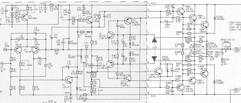
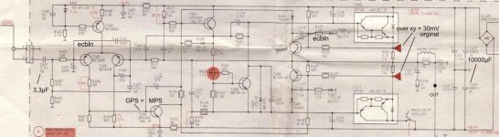
D3,D4 are antisaturation diodes. D5 helps to lower the hump at switch on (in conjuction with VAS starter circuit).
2EF presents low impedance for the VAS (runs at 3mA), the buffer stage increases that impedance.
Yes, I built and measured one module, no listening yet. I'm struggling with GND routing on the pcb, much more complicated than with symmetrical powering.
What amp can be seen in the post #95 ?
2EF presents low impedance for the VAS (runs at 3mA), the buffer stage increases that impedance.
Yes, I built and measured one module, no listening yet. I'm struggling with GND routing on the pcb, much more complicated than with symmetrical powering.
What amp can be seen in the post #95 ?
Last edited:
Does anyone remember a chip amplifier that bootstrapped the main supply rails for higher output? I can't find it. It was sort of a class-H amplifier but instead of high voltage rails, two additional outputs pushed up the rails with large bootstrap capacitors. I guess it didn't catch on.
1. Capacitors are paralleled because large capacitors have inductance that makes them high impedance at high frequencies. However, the frequencies where this happens is very high and so this idea is misguided for audio amplifiers.Hi all.
Why double capacitor in the bootstrap?
I have seen in the DX amplifier and other amplifiers, the use of a small capacitor in parallel to the main capacitor of the bootstrap. What is your function?
2. Some types of capacitors are slightly non-linear so the idea is to bypass the distortion they might generate. Again, the amount of distortion generated is actually trivial, and, paralleling with a much smaller capacitor does not significantly bypass the effect.
Remember that audio is full of unscientific and unproven ideas, reinforced by subjective bias. Many people believe things that they fail to prove when they take a double-blind test. On the other hand, inexperienced engineers fail to appreciate what is important and what is not. For example, many people prefer a bit of 2nd order distortion because musical sounds contain a lot of even order harmonics. This kind of distortion is expected/required in a guitar amplifier. It is the reason some people still prefer quasi-complimentary amplifier circuits.
Steveu
Thank you very much for your clear answer.
I agree with you when you say... that audio is full of unscientific and unproven ideas, reinforced by subjective bias.
Thank you very much for your clear answer.
I agree with you when you say... that audio is full of unscientific and unproven ideas, reinforced by subjective bias.
It's fine. 3 bootstraps. What is the reason for double bootatrap in the drivers? Any advantage?
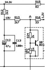
Not 3, 4 bootstraps. The negative voltage @ VT3 is also bootstrapped by C11. All 4 of these deal with the fact that he MOSFET gates need to be driven beyond the rails in order to saturate. Otherwise, the voltage swing is limited by the gate threshold, so you lose 4V+ output swing on each side. But as I think I mentioned before, a partial bootstrap like R13-R12 reduces the overdrive to avoid rail sticking. You don't need a whole 33V of bootstrap, only enough to drive the MOSFETs completely on. An alternate to bootstraps would be to use a (33+8=) +/-41V supplys for the driver and VAS.It's fine. 3 bootstraps. What is the reason for double bootatrap in the drivers? Any advantage?
Note that it would be more efficient if only two bootstraps were shared by the drivers and VAS.
Last edited:
Steveu.An alternate to bootstraps would be to use a (33+8=) +/-41V supplys for the driver and VAS
Interesting point. But I have not seen circuits with such a feature. It is not very common. Do you know any circuit or amplifier that applies what you mention?
I've seen several, typically a +/-40 rail with +/-50V VAS and driver supply. BJT amps often run the drivers off the main rails because the extra ~1V drop is not a big problem and power BJTs are slow to come out of saturation, and the VAS alone does not require very large BS caps. Years ago, the Yamaha P2200 had a boosted negative rail because the VAS was an NPN cascode. But they used a typical BS for the positive VAS and it was notorious for very bad rail sticking which soundmen blamed for horn failures. I had a fix that Yamaha grabbed because it was hurting sales. About the same time, the Crown DC300 had a positive rail boost for the VAS CCS. It's been 36 years since I left the audio business for the digital domain, so I don't know many newer amps, but I've seen several boosted rail circuits on DIYA and other web sites.Steveu.
Interesting point. But I have not seen circuits with such a feature. It is not very common. Do you know any circuit or amplifier that applies what you mention?
- Home
- Amplifiers
- Solid State
- Why bootstrap?