Hello,
I trying repair an amplifier
When i got it amp unit was short circuited, burning transistors
- changed many parts and got it running except bias reads ZERO!
So bias is 0.00v and doesnt react to the trimmer
- bias trimmer pot is tested and ok, resistors attached to bias circuit are ok, capasitor in bias circuit was changed
- dc offset is within limits and reacts to trimmer
- transistors were changed and tested too (with cheap component tester)
What could be the main causes for bias to stay at zero volts?
Attachments
Bias is fine...you wrote. Lots and lots of controversial claims.
https://www.diyaudio.com/community/threads/why-is-dc-offset-very-high-when-cold.404203/#post-7476011
https://www.diyaudio.com/community/threads/why-is-dc-offset-very-high-when-cold.404203/#post-7476011
I have 12 pieces of these amps here, two have high dc offset when cold and this one has no bias
So bias is not fine, so no "controversial claims" 🙂
I have biased many of these
So bias is not fine, so no "controversial claims" 🙂
I have biased many of these
I see, ok.
In that case if you have many, 12, at least few should be working perfectly. I suggest you select best working and measure voltages in all important spots. And write it into schematic and post it. As reference.
Than you do the same for amp with bias issue, and post. Same for amp with dc on output issue.
It should be easy to spot the differences.
If you can fix the transistor symbols, please do. Hard to look at, it burns my eyes.
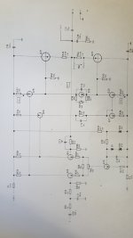
Have you checked for presence of voltage across the current-source emitter resistors: especially R27, but also R34, R36, R37, R40.
DoneIf you can fix the transistor symbols, please do. Hard to look at, it burns my eyes.

Two things I can think of:What could be the main causes for bias to stay at zero volts?
1/ The replacement (modern) transistors have slightly higher vbe due to manufacturing process differences. You just need to tweak the resistors around the vbe multiplier. Try reducing R39 to a 1k8. I would advise using a bulb tester.
2/ It looked that old I wondered if the originals were actually germaniums.
That doesn't really tell us much tbh.
You need around 0.6v across the b/e of each output transistor so if you measure between the base of each output (from base to base) you need to see the voltage rise to around 1.2 volts as you turn the preset before the output transistor will conduct.
You need around 0.6v across the b/e of each output transistor so if you measure between the base of each output (from base to base) you need to see the voltage rise to around 1.2 volts as you turn the preset before the output transistor will conduct.
I can't find the MJ2051, but apparently the MJ3001 is a silicon Darlington transistor. Unless the same holds for Q19, the bias voltage will be too small for Darlingtons (or at least too small to bias their output parts).
Are MJ2051 and MJ3001 the original transistor types?
Are MJ2051 and MJ3001 the original transistor types?
OK, it says that Q19 is also a Darlington transistor. That makes sense.
Did you replace Q19 and if so, by a Darlington transistor?
Did you replace Q19 and if so, by a Darlington transistor?
If they are Darlingtons then just place your meter across C15 and tell us what range of voltage you see with the preset at each end. With Darlingtons you will need to see around 2.5 volts to turn both on.
If you are measuring 0.000 volts, you are measuring a shorted wire./trace or some issue with your meter.
Any other measurement including open probes will read something but never 0.000.
Regards.
Any other measurement including open probes will read something but never 0.000.
Regards.
- Home
- Amplifiers
- Solid State
- Why bias stays zero, 0.00v and doesnt react to the bias trimmer?