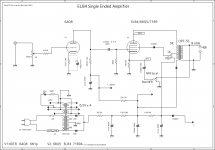
Why are there diodes on the screen and OPT here? I suspect it's to stop back EMF if the user switches between UL and pentode mode while the amp is playing? Am I right? Are there any sonic implications to having them there? I can't remember that I've ever seen this before even in my textbooks. Since the designer has a UL/pentode mode switch why didn't he just go ahead and add a triode mode too?
Attachments
I have built the older version of this schematic there was no possibility to choose UL / pentode and NFB even then there were diodes in the same place. I have had it explained to me why they are there and what it was good for but unfortunately I forgot about it but it sounds good anyway.
Someone can certainly explain both the pros and cons about it.
Someone can certainly explain both the pros and cons about it.
Diodes in series with a large inductor and nothing else?
Why do I fear inductive kicks will burn big holes through that junction if amp is overdriven into squarewave?
What was designer thinking?
Besides, screen to cathode is already a diode, not sure what an extra silicon one will accomplish.
Why do I fear inductive kicks will burn big holes through that junction if amp is overdriven into squarewave?
What was designer thinking?
Besides, screen to cathode is already a diode, not sure what an extra silicon one will accomplish.
This diodes are completely useless there. Also, a 50VW in the cathode where there is only 15 or 16V is stupid. A 25V unit will be better there. Also, a 4.68KΩ as a grid stopper 1% resistor for a huuuuuumble grid stopper???? Who did this design? Surely someone that likes spent money stupidly.
As far as I can tell, the diode on the screen is to prevent it from emitting. As far as 1% resistors, I use nothing else unless it's a metal oxide for power. 1% MF types are so cheap, why bother with 5%?
I've blown 100V caps on a cathode that was "only" 30V... If you oversize everything, a bad tube won't take out half the amp with it.
I've blown 100V caps on a cathode that was "only" 30V... If you oversize everything, a bad tube won't take out half the amp with it.
There are other errors. Like how the other channel goes through another RC filter... Maybe it's based on actual measurements, not stupidly precision parts. I didn't even think anything of it, I read it as 4k7.
Maybe they specced out that precision resistor simply because that's what they had on hand and used? I've got a sack of several hundred surplus precision Dales in 10K, so use them all over the place.
I think the idea is to prevent any circular flow of secondary electrons between screen and anode through the circuit, thus preventing damaging high currents in the screen grid.
If the screen grid is capable of emit electrons, then we are speaking of an overloaded screen (red wires) or the tube is gassy, in any instance it is a non conventional mode of being it active (the amp globally).
If the current through the diodes doesn't reverse (making the diode cut off), they don't do anything.
If the current does reverse, they wreak havoc.
I wouldn't even touch this circuit with a very long pole ...
Jan
If the current does reverse, they wreak havoc.
I wouldn't even touch this circuit with a very long pole ...
Jan
Who did this design?
Not sure, I'd have to trace it down. As a learner, I've been data-mining google images by tube number to just sit and read schematics by tube number. I couldn't explain this diode other than the fact that I know diodes are often installed across relay contacts, so I assumed it was something to do with a voltage spike caused by the UL switch there. But that's just a guess.
This diodes are completely useless there. Also, a 50VW in the cathode where there is only 15 or 16V is stupid. A 25V unit will be better there. Also, a 4.68KΩ as a grid stopper 1% resistor for a huuuuuumble grid stopper???? Who did this design? Surely someone that likes spent money stupidly.
All that, but the biggest money waster is four dedicated 6.3 volt windings, ouch.
All I can find on this is that it's also posted in the gallery under the username "keveas"
keveas SE EL84 6N1P - My Photo Gallery
I seem to remember seeing another version of the same without the screen wiring switch.
keveas SE EL84 6N1P - My Photo Gallery
I seem to remember seeing another version of the same without the screen wiring switch.
As far as the 1% resistors go, about 5 years ago I rebuilt my HK CIT I preamp. When I ordered the 1/4W metal film resistors from Digikey I noticed that the 1% resistors were cheaper than the 5%'s in the values that I needed.
All that, but the biggest money waster is four dedicated 6.3 volt windings, ouch.
Yes, as all them are grounded, one winding of the sum of the independent capacities is sufficient. Unless it be a toroidal trafo, where too large diameters are difficult to wind, several independent wires is easier.
Windcrest asked what the diodes are doing here and now some are about to throwing up on the schematic if the designer has done in a way you just have to accept this. But the site is a Japanese tube site in English and as far as I know there is a thread here with Japanese tube construction which is appreciated. But I have the link so everyone can watch EL84 Single Ended Amplifier D.I.Y
... the designer has done in a way you just have to accept this...[ /QUOTE]
No, nobody is obligated to maintain the circuit has been designed unless you are making an exact replica of it. Every circuit is perfectible. This implies taking away of superfluous elements like those diodes.
Reasons for putting those 1N4007 diodes in that schematic:
1. Someone has too many 1N4007 diodes and wants to sell them on the web.
2. There is an approximate 0.6V drop across the diode. Gets the voltage at the exact value the designer intended.
3. The designer has seen similar schematics that uses diodes in the screen, transformer primary, and B+ positions.
He copied the errors of others.
Just my opinion . . . take the diodes out, and use a straight piece of wire (which is a very small inductance).
- Home
- Amplifiers
- Tubes / Valves
- Why are these diodes here on the OPT?