Who here has built their own amp from their own design? I'm talking about from scratch not premade boards etc. Beside Mr Pass and Mr Curl, of course, has the true DIY spirit bitten anyone?
Yes, there is nothing new under the sun.Upupa Epops said:To markp : What do you mean as own design - all copy all 😀 .
I mean you took the time and effort to take a blank sheet of paper and figure out a circuit that would do what you wanted it to do and actually build it.
Maybe better question will be : who have any original mechanical / electrical construction, which is not crazy and have for it any logical explanation ? 😀
markp!
I haven't built anything designed by others since 1990. It was a TDA2003 amplifier.
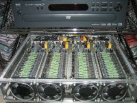
This is my latest product, (finished yesterday) a 2kW SMPS:
http://www.hszk.bme.hu/~sp215/elektro/SMPS_top.jpg
http://www.hszk.bme.hu/~sp215/elektro/SMPS_bottom.jpg
It's not final, it's only prototype. Even the inductors are made by myself. (PCB is only designed by me, but made by professionals.)
I haven't built anything designed by others since 1990. It was a TDA2003 amplifier.
This is my latest product, (finished yesterday) a 2kW SMPS:
http://www.hszk.bme.hu/~sp215/elektro/SMPS_top.jpg
http://www.hszk.bme.hu/~sp215/elektro/SMPS_bottom.jpg
It's not final, it's only prototype. Even the inductors are made by myself. (PCB is only designed by me, but made by professionals.)
markp said:Who here has built their own amp from their own design? I'm talking about from scratch not premade boards etc. Beside Mr Pass and Mr Curl, of course, has the true DIY spirit bitten anyone?
I have designed and built a few amps and pre-amps for my personal use. But, as anybody, I do not re-invent the wheel. I started my inspiration from schematics from what I have already seen. In fact, I have never been able to construct an amp based on a "public" schematics without modifying it a lot. I see (or maybe imagine...) always "flaws" in the design from either my experience or knowledge (at the time). What I like about analog audio design is that it is a bit like "art" sometimes and the goal (perfect amp) is probably unachievable (since the amp interfaces with imperfect things too: source signal and load). Lately, I decided the approach to use a "public" design and try to modify it (a lot, in fact) to experiment on the sound result.
Fab
Oops! I realised that the question was about amplifiers! Some of them are shown here: http://www.hszk.bme.hu/~sp215/elektro/index2.htm
pafi
how did you design your smps??..are they offline or dc-dc converters...do the data sheets help any?...
how did you design your smps??..are they offline or dc-dc converters...do the data sheets help any?...
I design and build my own stuff. Here is just one of many
http://gilmore.chem.northwestern.edu/dynahif2.jpg
http://gilmore.chem.northwestern.edu/dynahif2.jpg
When does it become "your own design"? Just about everything on the market commercially or in the public domain for DIY is derivative of something earlier. On the other hand, I've got a couple that while you will not find an identical circuit anywhere, will still look pretty familiar to most people here. To what extent are they original?
I must say that even something that is highly derivative of other designs can still take a huge amount of work and re-work before you get it functional.
I must say that even something that is highly derivative of other designs can still take a huge amount of work and re-work before you get it functional.
I built my own Class D amp in 1981. Hardly anyone else was messing with them then, and I could find precious little info to lead me in the right direction in those days.
kevin gilmore said:I design and build my own stuff. Here is just one of many
http://gilmore.chem.northwestern.edu/dynahif2.jpg
Damn. Show a little mercy. Not everyone's tied to a T3 and has a 30 inch monitor. That thing took me over 15 minutes. 🙂
Here's a more merciful version.
se
Attachments
ive built my own amp before, 90% distortion and unstable into loads below 16 ohms 🙂 was going to be a speaker amplifier first, then realising how bad it sounded i tried it with a set of headphones and it actually sounded semi-decent, got 89/100 for it as an assignment 😉
demons_wing said:pafi
how did you design your smps??..are they offline or dc-dc converters...do the data sheets help any?...
Yes, of course data sheets help much, but designing is more than copy the advised schematics in datasheets. Designing is copy the application notes! 😀 No, I'm just joking! It can't be told how to design SMPS in four steps.
My SMPS is an off-line converter. It operates from 230VAC, and produce 2*100VDC output.
EchoWars!
1981? impressive!
IMHO an own design is if you think about different input stage... combined with that sort of VAS and another output stage....
calculate it... select the components... design PCB and mechanics...
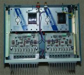
Here my old 8x150 design (1993), but still in use.
-OP input (OP37)
- Cascode BJT VAS, which is driven from the supply current of the OP amp 😀 😀 😀
- Output stage with ten paralleled BDW83D and BDW84D.
Each output transistor has 4 Ohms emitter resistors.... making 0.4 Ohms together. This allowed a low output impedance and a rugged short circuit proof design without additional current limit. Any desired output current available, can drive any crazy speaker.
The 8 amps can be combined (bridged, paralleled).
Any combination is possible up to 1 x 1200W into 2 Ohms.
In fact due to the heavy duty output stage you can drive also lower output impedances. Only the power supply may start to sweat.
But 2 x 1kVA toroids are not to poor.
Since 5 years I am driving a subwoofer with 1 Ohm and measured
1.8kW rms ......
calculate it... select the components... design PCB and mechanics...
Here my old 8x150 design (1993), but still in use.
-OP input (OP37)
- Cascode BJT VAS, which is driven from the supply current of the OP amp 😀 😀 😀
- Output stage with ten paralleled BDW83D and BDW84D.
Each output transistor has 4 Ohms emitter resistors.... making 0.4 Ohms together. This allowed a low output impedance and a rugged short circuit proof design without additional current limit. Any desired output current available, can drive any crazy speaker.
The 8 amps can be combined (bridged, paralleled).
Any combination is possible up to 1 x 1200W into 2 Ohms.
In fact due to the heavy duty output stage you can drive also lower output impedances. Only the power supply may start to sweat.
But 2 x 1kVA toroids are not to poor.
Since 5 years I am driving a subwoofer with 1 Ohm and measured
1.8kW rms ......
Attachments
Hmm,
I always try to make my life easier and say "this time I will do a kit". But I never do it. I always take some existing designs and modify it a lot, mix and match those elements I want in it, and I have only once or twice used a PCB. All else is veroboard.
But I have so far only have had one original idea (fro a way of using JFETs to switch resistors for a volume control), in the sense that I haven't seen it in this form anywhere else. It may have been invented many times before, just haven't seen it published. Since I haven't built a complete version of it yet I don't even know if it was a *good* idea 😉
There is many levels in innovation - new devices, new ways of using devices (topologies), new ways of using topologies (system building). So, the question is very hard to answer. Nuthin' new under the sun
Hmm, i somehow have the feeling, building a DIY-Amp from existing
kits or schematics is not real "done myself"...
But now i am working on my 9th amplifier, and its the first one
really working. They all had at least one of these 2 problems:
Stability or sounding. The only sound of one was a big "BANG" 🙁
I must admit, all these designs were inspired from existing ones.
I think for building an own design, you need somehow to be fanatic
or something like this ! (or a pro, but that's not me)
Today i believe, that it's an art to design a good amp, but what the hell,
it's a nice hobby.
Michael
- Status
- Not open for further replies.
- Home
- Amplifiers
- Solid State
- Who has built their own?