what daes mean "ground loading" in details ?
when I connect in xlr mode whitch is the correct posistion of S1 ?
when I connect in xlr mode whitch is the correct posistion of S1 ?
It loads the input, a bit like attenuate or decrease the input impedance and it makes no difference to XLR connection.
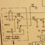
the diagram shows the triangle ground symbol attached to pin1 and ALSO attached to pin2, pin3 and RCA barrel.
This is wrong. It is "the Pin1 problem"
Build the Hummer and test your inputs/outputs for the pin 1 problem and rewire as necessary.
Pin1 ONLY connects to chassis.
Pins 2 & 3 and RCA only connect to the audio inputs and outputs.
At some other location you will probably find a separate connection between Chassis and Audio Ground. This is R38. This should be the ONLY direct connection from Pin1/Chassis to Audio Ground/return.
You will see in the pdf that this Pin1 problem analysis was introduced more than 20years ago and still there are commercial manufacturers getting Pin1 wrong. The note says
Don't buy equipment that has a Pin 1 problem - If you already own it, you may be able to perform some simple wiring changes to cure it.
Attachments
Last edited:
S1 switch operation.
S1 is connected to RCA barrel and to audio ground/return.
When S1 is to left R1 connects to audio ground. This is the same as R2 from pin3 to audio ground. This is the balanced mode.
Do not connect anything to RCA when in balanced mode. Pin1 to Chassis, Pin2 is signal hot, Pin3 is signal cold.
When S2 is to right, pin3 connects to audio ground/return. This is the unbalanced mode.
You can connect an input via the XLR, or via the RCA. Note "or". I suggest you do not use both, when in unbalanced mode.
RCA hot is the input signal flow and RCA barrel is the signal cold return.
The XLR, in unbalanced mode, is Pin1 to chassis, Pin2 is signal hot, Pin3 is signal cold/return.
Last edited:
hi AndrewT
When S1 is to left R1 connects to audio ground. This is the same as R2 from pin3 to audio ground. This is the balanced mode.
that in reale picturethe switch is connect in direction of xlr soket ?
When S1 is to left R1 connects to audio ground. This is the same as R2 from pin3 to audio ground. This is the balanced mode.
that in reale picturethe switch is connect in direction of xlr soket ?
Yes, both pin2 and pin3 have a resistor load connected to audio ground. This could be a 10M resistor to bleed off capacitor leakage, or it could be 600r (two 300r) to mimic a 600ohm balanced load for the balanced input, or anywhere in between........When S1 is to left R1 connects to audio ground. This is the same as R2 from pin3 to audio ground. This is the balanced mode.
I don't understand this sentence.that in reale picturethe switch is connect in direction of xlr soket ?
- Status
- Not open for further replies.
- Home
- Amplifiers
- Pass Labs
- who explaim me the function of s1