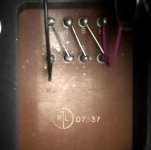
ok - so a bit more research has confirmed it's Ripley .....however they are out of business a long while back and so the hope I had was to see if the spec sheet was available for these.
However it seems not.
What I wanted to know is what the output impedance was set for ....I THINK it was likely 16 ohms as I had a pair of horn speakers at the time that were 16ohms and the amp was finished with these in mind.
Thoughts?
However it seems not.
What I wanted to know is what the output impedance was set for ....I THINK it was likely 16 ohms as I had a pair of horn speakers at the time that were 16ohms and the amp was finished with these in mind.
Thoughts?
Almost certainly 15-16 ohms (4 x 0.95-1 ohm windings connected in series). There are lots of other 4-section output transformers of that era with the same configuration.
So for an 8 ohm load(speaker) am I advised to change the output tap do you think, and is the topology of where to connect obvious?
Thanks!
Hope you are enjoying more sunshine than here in the UK at the moment!
Thanks!
Hope you are enjoying more sunshine than here in the UK at the moment!
Yes very sunny today and about 21°C 🙂. Connection for ~8 ohms is:
-Connect 2 to 3
-Connect 3 to 5
-Connect 4 to 6
-Connect 6 to 7
-Speaker to 1 and 8
-Connect 2 to 3
-Connect 3 to 5
-Connect 4 to 6
-Connect 6 to 7
-Speaker to 1 and 8
think I get it 🙂
This puts winding 3-4 in parallel to winding 5-6 and effectively in series as a parallel pair with 7-8 and 1-2?
Thanks, enjoy the sunshine 🙂
This puts winding 3-4 in parallel to winding 5-6 and effectively in series as a parallel pair with 7-8 and 1-2?
Thanks, enjoy the sunshine 🙂
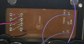
So I found this picture also regarding the secondary winding options, and made changes to the wiring to move to 8 ohms. Sounds better, BUT I noticed that the secondary might be out of phase, as the pink is +Ve and black is 0V GND
Will this make any difference, should I bother to try and swap the pink and black on the primary?
Thanks for all the know-how 🙂
Will this make any difference, should I bother to try and swap the pink and black on the primary?
Thanks for all the know-how 🙂
Attachments
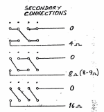
This drawing is by Partridge.
But isn't the 8 ohms wiring the same as described in post 5 ?
Check polarity by comparing input and output phase.
But isn't the 8 ohms wiring the same as described in post 5 ?
Check polarity by comparing input and output phase.
It does not matter too much if you are not sure about polarity of the whole system.
Easiest way to check is with a dual channel scope. Maybe REW has a similar feature.
Easiest way to check is with a dual channel scope. Maybe REW has a similar feature.
It does not matter too much if you are not sure about polarity of the whole system.
Easiest way to check is with a dual channel scope. Maybe REW has a similar feature.
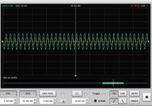
I have tried the dual channel scope of the REW software and applied a signal to the 211, and recorded the output from this channel. simultaneously I took a signal from the REW and straight back in (so connected input to output) on the other channel.
Before I did this I took input and output on both channels and saw the same signal and used the CH1-CH2 to show that the net was 0 or more correctly the trace of CH1-CH2, was pretty much flat line. This is of course to be expected as both channels are identical.
When I put one of the channels (CH2) through one channel of the 211, and compared the traces they look like they are in phase (with the reality that the 211 is obviously a larger amplitude on the output, as it has been amplified).
However when I look at CH1-CH2, my brain says the deduction should be in phase from the two traces but seems to be out of phase. Am i just being mathematically dumb? Obviously CH2 is larger so this will create a negative value, is this where the phase appears to change phase.....confused?
CH1 is blue
CH2 is yellow
CH1-CH2 is green
Attachments
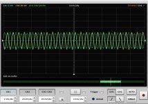
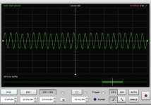
One or two full cycles are enough - otherwise it is hard to see.
noted, but the image hopefully still shows the fact that the green trace is out of phase with the yellow and blue traces.
it is more of a mathematical question, if I have a sine wave of magnitude say 1 and a sign wave of magnitude 5, and they are at the same frequency and in phase; then deducting 5 from 1 > should this still be in phase with 1 and 5 if they are truly in phase, or would this reverse the phase/
in other words does the CH1-CH2 trace expose that somehow CH1 is out of phase with CH2?
In other words, it is "obvious" that Ch1-Ch2 is of opposite phase compared to Ch2-Ch1,
but what you see on a scope screen will depend on triggering - may be also with REW.
but what you see on a scope screen will depend on triggering - may be also with REW.
In other words, it is "obvious" that Ch1-Ch2 is of opposite phase compared to Ch2-Ch1,
but what you see on a scope screen will depend on triggering - may be also with REW.
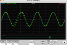
So what I saw with Ch1-Ch2 running the scope with a connection from output straight to input on the same trigger settings was a zero sum , so the green line representing Ch1-Ch2 was flat lined at 0.
Now the more I think about this the more I believe it is because Ch2 is a larger value and so the phase shift is because the subtraction of a larger negative value from a smaller positive creates a negative. So there is a negative where there was a positive and so appears out of phase?
What I will do is swap the Ch1 to the 211 and the Ch2 to the direct link, then my hypothesis is I will get the same phase.
Thoughts
- Home
- Amplifiers
- Tubes / Valves
- Which transformer brand is this?