I have a rotary encoder, and it has 7 wires coming out of it, all grey. There's no schematic available online, and I want to repurpose this encoder, but I don't know what does what.
Stupid question alert:
What's the right tool to help me figure out which wire is SIG, which is GND, which is 5v, etc etc ??
It's probably something simple like "Use an oscilloscope, and trial & error each wire while spinning the encoder both directions," but before I spend any money on even a cheap O-scope, I want to see if I'm on the right path.
Again: I don't need to do complicated measurements, I merely want to see which wire sends the output for a given action, and which wire is power-in (bonus if I can tell how much power).
Any help?
Or part number.
There are several ways these work. Simple switches, optical sensing, and so forth. "7 leads" is a part-clue but not complete.
There are several ways these work. Simple switches, optical sensing, and so forth. "7 leads" is a part-clue but not complete.
I think the point of my question wasn't clear.
Regardless what the component is...when one finds an unmarked component, what tool does one use to determine what pin does what?
Surely, one is ground, and surely one accepts voltage and surely at least one is a signal out, but what tool figures that out?
Thanks. Willing to try again if I'm still not being clear.
That is the point, to me it is not assured there will be ground and power pins, an encoder - to me - is a passive switch. Multipoled maybe but passive.
A typical encoder could be simple binary or maybe Gray Code, but in any case, just a switch, so the tool I use would be my ohm meter. I'd need to determine if it used a common or if it used more than one grouping of contacts. I'd want to know if it was a relative encoder or an absolute encoder.
And so that is why we'd like a photo, because if we knew what you had, we can make more informative responses.
If it is wired into a circuit, then I can use the voltages in the circuit to determine the function. Then I can use a scope or voltmeter.
How do you know it's an encoder? What sort of device did it come from? How big is it? Are the grey wires delicate or rugged? Does it spin freely or "cog" as you rotate the shaft? Enzo and PRR are offering good advice.
To reply more directly, a DVM (digital voltmeter) would be the first instrument to start with if you're starting with a complete unknown. With it, you can look for conduction between leads; resistance readings are clues; use meter connection polarity and the meter's diode test function to look for evidence that semiconductors are present. These experiments should lend at least some insight.
Good luck!
Last edited:
ok...
Let's use the specific 7-wire example; just took fresh pictures.
BUT! BUT BUT BUT...I'm not asking how to fix or debug this specific thing, I used it as an example so I can ask what tool/scope/thing I need, because I have a LOT of surplus gear and I want to repurpose it. If I can figure out how to do this thing, I should be pretty close to figuring out the other things.
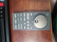
So let's take a look at what I have: it's a Sony RM-E9700 video editor remote control, which has a Jog/Shuttle wheel that I assume is an encoder. On the front, it looks like this:

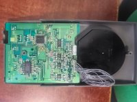
On the back, it looks like this (see the 7 grey wires?):

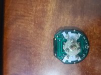
If I remove the encoder, it looks like this:

And if I turn it over, the PCB looks like this:

Behind the black plastic cover, there is no PCB, just a few resistors that you can probably guess the location of from the PCB image.
Thanks for your patience while I navigate a new site, new people, and new ways to upload images to help make my point.
Let's use the specific 7-wire example; just took fresh pictures.
BUT! BUT BUT BUT...I'm not asking how to fix or debug this specific thing, I used it as an example so I can ask what tool/scope/thing I need, because I have a LOT of surplus gear and I want to repurpose it. If I can figure out how to do this thing, I should be pretty close to figuring out the other things.
So let's take a look at what I have: it's a Sony RM-E9700 video editor remote control, which has a Jog/Shuttle wheel that I assume is an encoder. On the front, it looks like this:

On the back, it looks like this (see the 7 grey wires?):

If I remove the encoder, it looks like this:

And if I turn it over, the PCB looks like this:

Behind the black plastic cover, there is no PCB, just a few resistors that you can probably guess the location of from the PCB image.
Thanks for your patience while I navigate a new site, new people, and new ways to upload images to help make my point.
more answers
To finish answering:
The center dial spins freely (no indents), while the outer dial only has a limited range of motion which you MIGHT be able to see in the picture, sorta like 10:00-2:00, so it has 4 detents where those white lines are. It's otherwise smooth.
To finish answering:
The center dial spins freely (no indents), while the outer dial only has a limited range of motion which you MIGHT be able to see in the picture, sorta like 10:00-2:00, so it has 4 detents where those white lines are. It's otherwise smooth.
Use a DVM to measure the voltages at the pin header to figure out which is GND, V+, and the like. The other will be the "data" stuff.
It took me a moment or two to work out the logic , it seems the web is full of "re-purposing "/ recycling websites and "Eco friendly " types , usually American .
You name it if its electronic some other use can be made of it,even Scientific America has a web-page on it , I didn't realize it was so popular.
You name it if its electronic some other use can be made of it,even Scientific America has a web-page on it , I didn't realize it was so popular.
There isn't such a tool.Regardless what the component is...when one finds an unmarked component, what tool does one use to determine what pin does what?
I don't know about your part, possibly a logic analyzer may help, or just an ohmmeter.
Buy a cheap LCR meter at least it will give you a rough indication of what the component is.
Scroll down to #9 -big display not too dear its not in stock but it gives you an idea.-
https://www.amazon.com/CAMWAY-Capac...harge/dp/B07DVJB865/141-2505938-6357561?psc=1
Scroll down to #9 -big display not too dear its not in stock but it gives you an idea.-
https://www.amazon.com/CAMWAY-Capac...harge/dp/B07DVJB865/141-2505938-6357561?psc=1
If that thing has a LANC output, there could be ways to interface it with a PC for controlling media playback or editing.
- Home
- Design & Build
- Equipment & Tools
- Which tool does this?